Toyota Sienna Service Manual: Clearance Warning ECU Power Source Circuit
DESCRIPTION
This circuit provides power to the clearance warning ECU.
WIRING DIAGRAM

INSPECTION PROCEDURE
1 CHECK HARNESS AND CONNECTOR (CLEARANCE WARNING ECU - AIR CONDITIONER AMPLIFIER)

- Disconnect the connectors from the clearance warning ECU C9 and air conditioner amplifier connector A10 or A11.
- Measure the resistance according to the value(s) in the table below.
Standard resistance
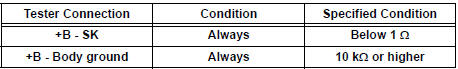
2 CHECK HARNESS AND CONNECTOR (CLEARANCE WARNING ECU - BODY GROUND)

- Measure the resistance according to the value(s) in the table below.
Standard resistance

3 INSPECT CLEARANCE WARNING ECU

- Disconnect the clearance warning ECU connector.
- Turn the ignition switch ON.
- Turn the clearance sonar main switch ON.
- Measure the voltage between terminals +B and E of the ECU.
Standard voltage: 10 to 14 V
Result

PROCEED TO NEXT CIRCUIT INSPECTION SHOWN IN PROBLEM SYMPTOMS TABLE
4 INSPECT PRINTED WIRE INTEGRATION BOARD SUB-ASSEMBLY
- Check that the malfunction disappears when a known good printed wire integration board sub-assembly is installed.
OK: Malfunction disappears
REPLACE PRINTED WIRE INTEGRATION BOARD SUB-ASSEMBLY
5 INSPECT INTEGRATION PANEL SUB-ASSEMBLY
- Check that the malfunction disappears when a known good integration panel sub-assembly is installed.
OK: Malfunction disappears.
REPLACE INTEGRATION PANEL SUB-ASSEMBLY
 No. 1 Clearance Warning Buzzer Circuit
DESCRIPTION
The clearance warning ECU receives the ultrasonic sensor signal to sound the
front warning buzzer.
WIRING DIAGRAM
INSPECTION PROCEDURE
1 INSPECT FRONT BUZZER
Remove the c ...
 No. 2 Clearance Warning Buzzer Circuit
DESCRIPTION
The clearance warning ECU receives the ultrasonic sensor signal to sound the
rear warning buzzer.
WIRING DIAGRAM
INSPECTION PROCEDURE
1 CHECK HARNESS AND CONNECTOR (CLEARANCE WAR ...
Other materials:
Display Panel does not Open, Tilt or Tilts Improperly
INSPECTION PROCEDURE
1 CHECK RADIO AND NAVIGATION ASSEMBLY
Check for foreign matter or obstructions caught in the
moving parts of the panel.
OK:
No obstruction or foreign matter found.
2 CHECK OPERATION
Check if the navigation and audio systems function
properly.
OK:
Naviga ...
Back Door Closer does not Operate
DESCRIPTION
The power back door ECU controls the back door closer system. In response to
the signals output from
the switches related to the back door lock, the back door latch activates the
closer motor.
HINT:
The back door closer system operates regardless of whether the power back door
...
Front Airbag Sensor RH Circuit Malfunction
DTC B1148/36 Front Airbag Sensor RH Circuit Malfunction
DESCRIPTION
The front airbag sensor RH circuit consists of the center airbag sensor
assembly and front airbag sensor
RH. If the center airbag sensor assembly receives signals from the front airbag
sensor RH, it judges
whether or not the ...