Toyota Sienna Service Manual: Diagnosis system
1. CHECK DLC3
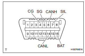
(a) The vehicle's ECM uses the ISO 15765-4 for communication. The terminal arrangement of the DLC3 complies with SAE J1962 and matches the ISO 15765-4 format.
HINT: Connect the cable of the intelligent tester to the DLC3, turn the ignition switch to the ON position and attempt to use the tester. If the display indicates that a communication error has occurred, there is a problem either with the vehicle or with the tester.
If communication is normal when the tester is connected to another vehicle, inspect the DLC3 of the original vehicle.
If communication is still not possible when the tester is connected to another vehicle, the problem may be in the tester itself. Consult the Service Department listed in the tester's instruction manual.

NOTICE: *: Before measuring the resistance, leave the vehicle as is for at least 1 minute and do not operate the ignition switch, any other switches or the doors.
 Terminals of ecu
1. A/C AMPLIFIER
(a) Waveform 1:
(b) Waveform 2:
(c) Waveform 3: ...
 Dtc check / clear
1. DTC CHECK (SENSOR CHECK)
(a) After the indicator check is completed, the system
enters the DTC check mode automatically.
(b) Read the codes displayed on the panel. Refer to the
list of co ...
Other materials:
Disassembly
HINT:
Overhaul the RH side by the same procedures as these of
the LH side.
1. REMOVE REAR WHEEL
2. SEPARATE REAR DISC BRAKE CALIPER
ASSEMBLY LH
HINT:
Do not disconnect the flexible hose from the brake
caliper.
3. REMOVE REAR DISC
(a) Release the parking brake, and remove the rear
disc.
H ...
Transmission Range Sensor Circuit Malfunction
(PRNDL Input)
DESCRIPTION
The park/neutral position switch detects the shift lever position and sends
signals to the ECM.
MONITOR DESCRIPTION
These DTCs indicate a problem with the park/neutral position switch and the
wire harness in the park/
neutral position switch circuit.
The park/neutral po ...
Removal
1. DRAIN AUTOMATIC TRANSAXLE FLUID (See page
AX-131)
2. REMOVE NO. 1 TRANSFER CASE PLUG (See page
TF-8)
3. REMOVE TRANSFER DRAIN PLUG
(a) Remove the transfer drain plug, gasket and bleed
the drain transfer oil.
4. REMOVE FRONT WHEEL
5. REMOVE FRONT DRIVE SHAFT ASSEMBLY RH
HINT:
(See page D ...