Toyota Sienna Service Manual: Disassembly
1. Remove repair service starter kit

(a) Remove the nut and disconnect the lead wire from the repair service starter kit.

(b) Remove the 2 screws which are used to secure the repair service starter kit to the repair service starter kit.
(c) Remove the repair service starter kit.
(d) Remove the return spring and the plunger from the repair service starter kit.
2. REMOVE STARTER YOKE ASSEMBLY

(a) Remove the 2 through bolts and pull out the starter yoke together with the starter commutator end frame.

(b) Remove the starter yoke from the starter commutator end frame.
3. REMOVE STARTER ARMATURE PLATE

(a) Remove the starter armature plate from the starter yoke.
4. REMOVE DRIVE HOUSING STARTER BEARING COVER

(a) Using a screwdriver, remove the drive housing starter bearing cover.
5. REMOVE STARTER ARMATURE ASSEMBLY
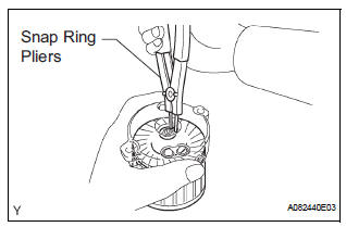
(a) Using snap ring pliers, remove the snap ring and plate washer.
(b) Remove the starter armature from the commutator end frame.
6. REMOVE PLANETARY GEAR

(a) Remove the 3 planetary gears from the repair service starter kit.
 Removal
1. REMOVE BATTERY (See page EM-26)
2. REMOVE NO. 2 AIR CLEANER INLET (See page EM-
28)
3. REMOVE AIR CLEANER CAP SUB-ASSEMBLY (See
page FU-13)
4. REMOVE AIR CLEANER FILTER ELEMENT (See page
EM-2 ...
 Inspection
1. Inspect starter assembly
NOTICE:
These tests must be performed within 3 to 5 seconds
to avoid burning out the coil.
(a) Perform the pull-in test.
(1) Disconnect the lead ...
Other materials:
Short in Rear Curtain Shield Squib RH Circuit
DTC B1630/83 Short in Rear Curtain Shield Squib RH Circuit
DESCRIPTION
The rear curtain shield squib RH circuit consists of the center airbag sensor
assembly and the curtain
shield airbag assembly RH.
The circuit instructs the SRS to deploy when deployment conditions are met.
DTC B1630/83 ...
Disassembly
1. REMOVE COOLER THERMISTOR NO.1 (for Automatic Air Conditioning System)
(a) Disengage the 2 claw fittings and the clamp and
remove the cooler thermistor No. 1.
2. REMOVE COOLING UNIT MOTOR SUB-ASSEMBLY WITH FAN
(a) Remove the 3 screws and the cooling unit motor
sub-assembly w/ fan.
3. ...
SRS Warning Light does not Come ON
DESCRIPTION
WIRING DIAGRAM
INSPECTION PROCEDURE
1 CHECK BATTERY
Measure the voltage of the battery.
Standard voltage:
11 to 14 V
CHECK AND REPLACE BATTERY OR
CHARGING SYSTEM
2 CHECK CONNECTORS
Turn the ignition switch to the LOCK position.
Disconnect the negative (-) term ...