Toyota Sienna Service Manual: Display Signal Circuit between Radio and Navigation Assembly and Television Camera Assembly
DESCRIPTION
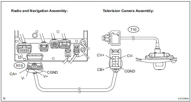
This is the display signal circuit of the television camera assembly.
WIRING DIAGRAM

INSPECTION PROCEDURE
1 CHECK HARNESS AND CONNECTOR (RADIO AND NAVIGATION ASSEMBLY - TELEVISION CAMERA ASSEMBLY)
- Disconnect the R10 connector from the radio and navigation assembly.
- Disconnect the T10 connector from the television camera assembly.
- Measure the resistance according to the value(s) in the table below.
Standard resistance

2 INSPECT RADIO AND NAVIGATION ASSEMBLY
- Reconnect the radio and navigation assembly R10 connector.

- Measure the voltage according to the value(s) in the table below
Standard voltage

3 INSPECT TELEVISION CAMERA ASSEMBLY
- Reconnect the radio and navigation assembly R10 connector and the television camera assembly T10 connector.

- Check the waveform of the television camera assembly using an oscilloscope.

- Measurement terminal: CV+ - CVMeasurement setting: 0.2 V/DIV, 0.2 μs/DIV Condition: Ignition switch ON, Shift lever in R range
OK: Pulses as shown in the illustration.
PROCEED TO NEXT CIRCUIT INSPECTION SHOWN IN PROBLEM SYMPTOMS TABLE
 Reverse Signal Circuit
DESCRIPTION
The radio and navigation assembly receives a reverse signal from the
park/neutral position switch.
WIRING DIAGRAM
INSPECTION PROCEDURE
1 INSPECT RADIO AND NAVIGATION ASSEMBLY
...
 Clearance warning ECU
COMPONENTS
REMOVAL
1. REMOVE FRONT DOOR SCUFF PLATE LH
2. REMOVE COWL SIDE TRIM BOARD LH
3. REMOVE INSTRUMENT PANEL FINISH PANEL SUBASSEMBLY LOWER LH
4. REMOVE NO. 1 INSTRUMENT PANEL SAFETY PAD ...
Other materials:
Airbag ECU Communication Stop
DTC B1281 Airbag ECU Communication Stop
DESCRIPTION
DTC B1281 is output when communication between the airbag ECU and the
multiplex network gateway
ECU stops for more than 10 seconds.
DTC No.
DTC Detection Condition
Trouble Area
B1281
Airbag ECU communi ...
Setting the vehicle speed
Press the “ON-OFF” button to
activate the cruise control.
Cruise control indicator will come
on*1 or will be displayed on the
multi-information display*2.
Press the button again to deactivate
the cruise control.
Accelerate or decelerate the
vehicle to the desired s ...
Initialization not Completed
DTC C2177/77 Initialization not Completed
DESCRIPTION
Initialization is necessary after replacing any of the ECUs, tires with
different tire pressure, or tire pressure
warning valve and transmitter, after rotating the tires or when a new vehicle is
delivered.
WIRING DIAGRAM
INSPECTI ...