Toyota Sienna Service Manual: DRL Relay Circuit
DESCRIPTION
The Multiplex network body ECU controls the DRL No.2 relay
WIRING DIAGRAM

INSPECTION PROCEDURE
1 PERFORM ACTIVE TEST BY INTELLIGENT TESTER
- Connect the intelligent tester to DLC3.
- Turn the ignition switch ON and push the intelligent tester main switch ON.
- Select the item below in the ACTIVE TEST and then check that the relay operates.
BODY NO.1:

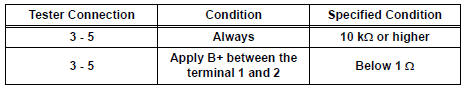
2 INSPECT DRL NO.2 RELAY

- Inspect DRL No.2 Relay continuity.
Resistance
3 CHECK HARNESS AND CONNECTOR (POWER SOURCE)

- Disconnect the connector from the instrument panel junction block assembly.
- Measure the voltage according to the value(s) in the table below.
Voltage

4 INSPECT INSTRUMENT PANEL JUNCTION BLOCK ASSEMBLY
- Reconnect the connector to the instrument panel junction block assembly.

- Measure the voltage according to the value(s) in the table below.
Voltage


5 INSPECT RELAY (DRL NO.3, DRL NO.4)

- Inspect DRL NO.4 Relay continuity.
Resistance

- Inspect DRL NO.3 Relay continuity.

Resistance

6 INSPECT DAYTIME RUNNING LIGHT RESISTER

- Measure the resistance according to the value(s) in the table below.
Resistance

REPAIR OR REPLACE HARNESS OR CONNECTOR
 Headlight Relay Circuit
DESCRIPTION
The Multiplex network body ECU controls HEAD relay when signal is received
from headlight dimmer
switch assembly.
WIRING DIAGRAM
INSPECTION PROCEDURE
1 PERFORM ACTIVE TEST BY IN ...
 Front Fog Light Circuit
DESCRIPTION
The Multiplex network body ECU controls FOG relay when signal is received
from headlight dimmer
switch assembly.
WIRING DIAGRAM
INSPECTION PROCEDURE
1 PERFORM ACTIVE TEST BY INT ...
Other materials:
Disposal
HINT:
On the RH side, use the same procedures as on the LH side.
1. DISPOSE OF BACK DOOR STAY SUB-ASSEMBLY LH
Horizontally fix the stay in a vise with the piston-rod
pulled out.
Wearing safety glasses, gradually cut a part
between A and B as shown in the illustration using a
metal ...
Diagnostic trouble code chart
HINT:
If a malfunction code is displayed during the DTC check,
check the circuit indicated by the DTC. For details of each
code, turn to the page for the respective "DTC Code" in the
DTC chart.
DTC chart of ABS:
DTC chart of VSC:
...
Installation
1. INSTALL TRANSAXLE HOUSING OIL SEAL
(a) Using SST and a hammer, install a new oil seal.
SST 09316-60011 (09316-00011)
Oil seal installation depth:
-0.5 to 0.5 mm (-0.020 to 0.020 in.)
(b) Coat the lip of the oil seal with MP grease.
2. INSTALL DIFFERENTIAL SIDE BEARING RETAINER OIL SEA ...