Toyota Sienna Service Manual: ECM / PCM Internal Engine Off Timer Performance
DTC SUMMARY
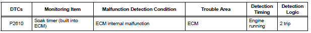
DESCRIPTION
To ensure the accuracy of the EVAP (Evaporative Emission) monitor values, the soak timer, which is built into the ECM, measures 5 hours (+/- 15 minutes) from when the ignition switch is turned off, before the monitor is run. This allows the fuel to cool down, which stabilizes the Fuel Tank Pressure (FTP). When 5 hours have elapsed, the ECM turns on.

MONITOR DESCRIPTION
5 hours after the ignition switch is turned off, the soak timer activates the ECM to begin the EVAP system monitor. While the engine is running, the ECM monitors the synchronization of the soak timer and the CPU clock. If these two are not synchronized, the ECM interprets this as a malfunction, illuminates the MIL and sets the DTC (2 trip detection logic).
MONITOR STRATEGY

TYPICAL ENABLING CONDITIONS

TYPICAL MALFUNCTION THRESHOLDS

INSPECTION PROCEDURE
HINT:
- DTC P2610 is set if an internal ECM problem is detected. Diagnostic
procedures are not required.
ECM replacement is required.
- Read freeze frame data using the intelligent tester. The ECM records vehicle and driving condition information as freeze frame data the moment a DTC is stored. When troubleshooting, freeze frame data can be helpful in determining whether the vehicle was running or stopped, whether the engine was warmed up or not, whether the air-fuel ratio was lean or rich, as well as other data recorded at the time of a malfunction.
1 REPLACE ECM
(a) Replace the ECM (See page ES-498).

2 CHECK WHETHER DTC OUTPUT RECURS
(a) Connect the intelligent tester to the DLC3.
(b) Turn the ignition switch to the ON position.
(c) Clear the DTCs (See page ES-39).
(d) Start the engine and wait for 10 minutes or more.
(e) Select the following menu items on the tester: DIAGNOSIS / ENHANCED OBD II / DTC INFO / PENDING CODES.
(f) If no pending DTC is displayed, the repair has been successfully completed.
OK: No DTC output.


END
 Evaporative Emission System Switching Valve Control Circuit High
DTC SUMMARY
DESCRIPTION
The circuit description can be found in the EVAP (Evaporative Emission)
System (See page ES-404).
INSPECTION PROCEDURE
Refer to the EVAP System (See page ES-404). ...
 A/F Sensor Circuit Slow Response
HINT:
DTC P2A00 indicates malfunctions related to the bank 1 A/F sensor.
DTC P2A03 indicates malfunctions related to the bank 2 A/F sensor.
Bank 1 refers to the bank that includes cylinder ...
Other materials:
Diagnosis system
DESCRIPTION
(a) When troubleshooting OBD II (On-Board
Diagnostics) vehicles, an intelligent tester
(complying with SAE J1987) must be connected to
the DLC3 (Data Link Connector 3) of the vehicle.
Various data in the vehicle's ECM (Engine Control
Module) can be then read.
(b) OBD II regu ...
DTC check / clear
1. CHECK DTC
Connect the intelligent tester to the Controller Area
Network Vehicle Interface Module (CAN VIM). Then
connect the CAN VIM to the DLC3.
Turn the ignition switch on.
Turn the tester ON.
Enter the following menu items: DIAGNOSIS / OBD/
MOBD / IM ...
Front wheel alignment
Adjustment
NOTICE:
For vehicles equipped with VSC, if wheel alignment has
been adjusted, and if suspension or underbody
components have been removed/installed or replaced, be
sure to perform the following initialization procedure in
order for the system to function normally:
1. Disconnect the ...