Toyota Sienna Service Manual: Fuel pump resistor
Components

REMOVAL
1. REMOVE FUEL PUMP RESISTOR
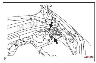
(a) Disconnect the connector.
(b) Remove the nut and fuel pump resistor.
INSPECTION
1. INSPECT FUEL PUMP RESISTOR

(a) Inspect fuel pump resistor.
(1) Using an ohmmeter, measure the resistance between the terminals.
Standard resistance

INSTALLATION
1. INSTALL FUEL PUMP RESISTOR

(a) Install the fuel pump resistor with nut.
Torque: 7.5 N*m (76 kgf*cm, 66 in.*lbf) (b) Connect the connector.
 Installation
1. INSTALL FUEL TANK ASSEMBLY (See page FU-44)V
2. INSPECT FOR FUEL LEAK (See page FU-7)
3. INSTALL FUEL TANK FILLER HOSE COVER (See
page FU-45)
4. INSTALL REAR FLOOR NO. 2 CROSSMEMBER
BRACE LH ( ...
 Fuel tank
Components
REMOVAL
1. DISCHARGE FUEL SYSTEM PRESSURE
(See page FU-1)
2. REMOVE CHARCOAL CANISTER PROTECTOR (See
page FU-30)
3. REMOVE REAR FLOOR NO. 2 CROSSMEMBER BRACE LH
(a) Remov ...
Other materials:
Replacement
1. REPLACE GENERATOR DRIVE END FRAME BEARING
(a) Remove the 4 screws and retainer plate from the
drive end frame.
(b) Using SST and a hammer, tap out the drive end
frame bearing from the drive end frame.
SST 09950-60010 (09951-00250), 09950-70010
(09951-07100)
(c) Using SST and a ...
VSC Warning Light Remains ON
DESCRIPTION
The skid control ECU is connected to the combination meter via CAN and
multiplex communications.
If the skid control ECU stores DTCs to shut down TRAC and VSC operation, the VSC
warning light comes
on in the combination meter.
WIRING DIAGRAM
INSPECTION PROCEDURE
NOTICE:
...
Power Source Circuit
DESCRIPTION
Power is supplied to the fold seat control ECU through the L-RR2 SEAT and
R-RR2 SEAT fuses.
WIRING DIAGRAM
INSPECTION PROCEDURE
1 INSPECT FUSE (L-RR2 SEAT, R-RR2 SEAT)
Remove the fuses from the R/B No. 3.
Measure the resistance according to the value(s) in the
...