Toyota Sienna Service Manual: Ignition Switch Circuit
DESCRIPTION
When the ignition switch is turned to the ON position, battery positive voltage is applied to terminal IG of the ECU. When battery positive voltage is applied to terminal IG of the ECU while the theft deterrent system is operating, the warning stops.
WIRING DIAGRAM

INSPECTION PROCEDURE
1 INSPECT FUSES (ECU-IG, AM1)
- Remove the ECU-IG and AM1 fuses from the instrument panel J/B.
- Measure the resistance.
Standard resistance: Below 1 Ω
2 INSPECT RELAY (IG1)

- Remove the IG1 relay from the instrument panel J/B.
- Check the operation of the IG1 relay.
Standard resistance

3 INSPECT IGNITION OR STARTER SWITCH ASSEMBLY
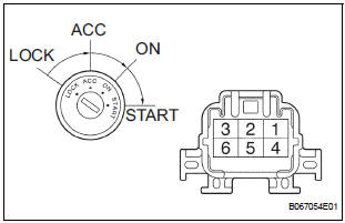
- Disconnect the I15 switch connector.
- Measure the resistance according to the value(s) in the table below.
Standard resistance

4 CHECK INSTRUMENT PANEL JUNCTION BLOCK ASSEMBLY (POWER SOURCE)
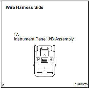
- Disconnect the 1A J/B connector.
- Turn the ignition switch ON.
- Measure the voltage according to the value(s) in the table below.
Standard voltage

REPLACE INSTRUMENT PANEL J/B ASSEMBLY
 Security Horn Circuit
DESCRIPTION
During the alarm sounding state, the relay in the ECU turns on and off in a
cycle of approximately 0.2
seconds, causing the security horn to sound.
WIRING DIAGRAM
INSPECTION PROC ...
 Security Indicator Light Circuit
DESCRIPTION
Even when the theft deterrent system is in the disarmed state, the security
indicator blinks due to a signal
output from the immobiliser system. The security indicator blinks continuou ...
Other materials:
Intermediate Shaft Speed Sensor "A"
DESCRIPTION
This sensor detects the rotation speed of the counter gear. By comparing the
counter gear speed signal
(NC) with the direct clutch speed sensor signal (NT), the ECM detects the shift
timing of the gears and
appropriately controls the engine torque and hydraulic pressure according ...
Short to GND in Front Passenger Side Squib
Circuit
DTC B0107/51 Short to GND in Front Passenger Side Squib
Circuit
DESCRIPTION
The front passenger side squib circuit consists of the center airbag sensor
assembly and the front
passenger airbag assembly.
The circuit instructs the SRS to deploy when deployment conditions are met.
DTC B0107/ ...
Engine unit
COMPONENTS
...