Toyota Sienna Service Manual: Installation
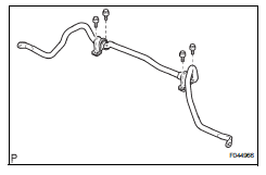
1. INSTALL FRONT STABILIZER BAR
2. INSTALL NO. 1 FRONT STABILIZER BAR BUSHING
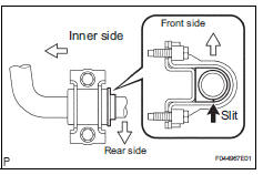
(a) Install the 2 front stabilizer bar bush No.1 to the stabilizer bar front.
NOTICE: Install the bushings with the slit facing on the rear side of the vehicle.
HINT: Install the bushing to the outer side of the bushing stopper on the stabilizer bar as shown in the illustration.
3. INSTALL EXHAUST MANIFOLD SUB-ASSEMBLY RH
HINT: (See page EM-48)
4. INSTALL MANIFOLD STAY
HINT: (See page EM-51)
5. INSTALL STEERING INTERMEDIATE SHAFT ASSEMBLY
HINT: (See page PS-21)
6. INSTALL RACK & PINION POWER STEERING GEAR ASSEMBLY
HINT: (See page PS-21)
7. CONNECT PRESSURE FEED TUBE ASSEMBLY
HINT: (See page PS-21) SST 09023-12701
8. INSTALL TIE ROD ASSEMBLY LH
HINT: (See page AH-4)
9. INSTALL TIE ROD ASSEMBLY RH
HINT: Remove the RH side by the same procedures as the LH side.
10. INSTALL NO. 1 FRONT STABILIZER BRACKET LH
(a) Install the front stabilizer bracket No.1 LH with the 2 bolts.
Torque: 17 N*m (173 kgf*cm, 12 ft.*lbf)
11. INSTALL NO. 1 FRONT STABILIZER BRACKET RH
HINT: Install the RH side by the same procedures as the LH side.
12. INSTALL CENTER EXHAUST PIPE ASSEMBLY
HINT: (See page EX-10)
13. INSTALL FRONT STABILIZER LINK ASSEMBLY LH
HINT: (See page AH-4)
14. INSTALL FRONT STABILIZER LINK ASSEMBLY RH
HINT: Install the RH side by the same procedures as the LH side.
15. INSTALL FRONT WHEELS
16. INSPECT CENTER FRONT WHEEL
17. INSPECT STEERING WHEEL CENTER POINT
18. ADD POWER STEERING FLUID
19. BLEED POWER STEERING FLUID
HINT: (See page PS-6)
20. CHECK POWER STEERING FLUID LEAKAGE
21. INSPECT AND ADJUST FRONT WHEEL ALIGNMENT
HINT: (See page SP-4)
 Inspection
1. INSPECT FRONT STABILIZER LINK ASSEMBLY LH
(a) As shown in the illustration, flip the ball joint stud
back and forth 5 times, before installing the nut.
(b) Using a torque wrench, turn the nut ...
 Rear coil spring
COMPONENTS
...
Other materials:
Air conditioning unit
COMPONENTS
...
Installation
1. INSTALL REAR NO. 1 SEAT ASSEMBLY LH
Place the seat in the cabin.
NOTICE:
Be careful not to damage the body.
Install the seat.
7-Passenger RH:
Install the seat belt anchor plate with the bolt.
Torque: 42 N*m (428 kgf*cm, 31 ft.*lbf)
Install the headrest. ...
Short to GND in Curtain Shield Squib RH Circuit
DTC B1162/81 Short to GND in Curtain Shield Squib RH Circuit
DESCRIPTION
The curtain shield squib RH circuit consists of the center airbag sensor
assembly and the curtain shield
airbag assembly RH.
The circuit instructs the SRS to deploy when deployment conditions are met.
DTC B1162/81 is ...