Toyota Sienna Service Manual: Installation
1. INSTALL REAR AXLE BEAM DAMPER
(a) Install the rear axle beam damper to the rear axle beam assembly.
2. INSTALL REAR AXLE CARRIER BUSH LH

(a) Align the matchmarks on the axle beam assembly with the 2 notches of a new bushing and temporarily install the bushing to the rear axle beam assembly.
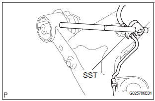
(b) Using SST, install the bushing to the axle beam.
SST 09710-04101, 09950-40011 (09951-04020, 09952-04010, 09953-04030, 09954-04020, 09955-04051, 09957-04010, 09958-04011), 09950-60010 (09951-00620)
NOTICE:
- Hang the claw of SST to the bushing securely.
- Do not scratch the rubber portion of the bushing.
- Do not deform the bushing rib.
3. INSTALL REAR AXLE CARRIER BUSH RH
SST 09710-04101, 09950-40011 (09951-04020, 09952-04010, 09953-04030, 09954-04020, 09955-04051, 09957-04010, 09958-04011), 09950-60010 (09951-00620)
HINT: Install the RH side by the same procedures as the LH side.
4. INSTALL REAR BRAKE TUBE FLEXIBLE HOSE
(a) Install the flexible hose and clip.
(b) Using SST, connect the brake tube to the flexible hose.
Torque: 15 N*m (153 kgf*cm, 11 ft.*lbf) SST 09023-00101
HINT: Install the RH side by the same procedures as the LH side.
5. TEMPORARILY TIGHTEN REAR AXLE BEAM ASSEMBLY
(a) Support the rear axle beam assembly with a jack.
(b) Install the rear axle beam assembly, 2 bolts and temporary tighten the 2 nuts.
6. INSTALL COIL SPRING REAR LH
HINT: (See page SP-38)
7. INSTALL COIL SPRING REAR RH
HINT: Install the RH side by the same procedures as the LH side.
8. CONNECT SHOCK ABSORBER ASSEMBLY REAR LH
HINT: (See page SP-38)
9. CONNECT SHOCK ABSORBER ASSEMBLY REAR RH
HINT: Connect the RH side by the same procedures as the LH side.
10. INSTALL BRAKE BACKING PLATE SUB-ASSEMBLY REAR LH (for DRUM REAR BRAKE)
(a) Install the 2 rear axle bearing retainer inner LH and parking brake plate sub-assembly LH.
11. INSTALL BRAKE BACKING PLATE SUB-ASSEMBLY REAR RH (for DRUM REAR BRAKE)
HINT: Install the RH side by the same procedures as the LH side.
12. INSTALL PARKING BRAKE PLATE SUB-ASSEMBLY LH (for DISC REAR BRAKE)
(a) 2WD DRIVE TYPE: Install the 2 rear axle bearing retainer inner LH and parking brake plate subassembly LH to the rear axle beam assembly.
(b) 4WD DRIVE TYPE: Install the rear axle bearing retainer outer and parking brake plate sub-assembly LH to the rear axle beam assembly.
13. INSTALL PARKING BRAKE PLATE SUB-ASSEMBLY RH (for DISC REAR BRAKE)
HINT: Install the RH side by the same procedures as the LH side.
14. INSTALL REAR AXLE HUB & BEARING ASSEMBLY LH (for 2WD)
HINT: (See page AH-15)
15. INSTALL REAR AXLE HUB & BEARING ASSEMBLY RH (for 2WD)
HINT: Install the RH side by the same procedures as the LH side.
16. INSTALL REAR AXLE HUB & BEARING ASSEMBLY LH (for 4WD)
HINT: (See page AH-18)
17. INSTALL REAR AXLE HUB & BEARING ASSEMBLY RH (for 4WD)
HINT: Install the RH side by the same procedures as the LH side.
18. INSTALL REAR BRAKE DRUM SUB-ASSEMBLY (for DRUM REAR BRAKE) 19. INSTALL REAR DISC (for DISC REAR BRAKE)
20. INSTALL REAR DISC BRAKE CALIPER ASSEMBLY LH (for DISC REAR BRAKE)
(a) Install the 2 bolts and rear disc brake caliper assembly LH to the rear axle beam assembly.
Torque: 88 N*m (897 kgf*cm, 65 ft.*lbf)
21. INSTALL REAR DISC BRAKE CALIPER ASSEMBLY RH (for DISC REAR BRAKE)
HINT: Install the RH side by the same procedures as the LH side.
22. CONNECT REAR BRAKE TUBE NO.2
HINT: (See page SP-38) SST 09023-00101
23. CONNECT REAR BRAKE TUBE NO.1 SST 09023-00101
HINT: Connect the RH side by the same procedures as the LH side.
24. INSTALL PARKING BRAKE CABLE ASSEMBLY NO.3
HINT: (See page SP-38)
25. INSTALL PARKING BRAKE CABLE ASSEMBLY NO.2
HINT: Install the RH side by the same procedures as the LH side.
26. INSTALL DIFFERENTIAL CARRIER ASSEMBLY REAR (for 4WD)
HINT: (See page DF-8)
27. INSTALL REAR DRIVE SHAFT ASSEMBLY LH (for 4WD)
HINT: (See page AH-18)
28. INSTALL REAR DRIVE SHAFT ASSEMBLY RH (for 4WD)
HINT: Install the RH side by the same procedures as the LH side.
29. INSTALL REAR AXLE SHAFT LH NUT (for 4WD)
HINT: (See page AH-18)
30. INSTALL REAR AXLE SHAFT RH NUT (for 4WD)
HINT: Install the RH side by the same procedures as the LH side.
31. INSTALL PROPELLER W/CENTER BEARING SHAFT ASSEMBLY (for 4WD)
32. CONNECT SKID CONTROL SENSOR WIRE (for 2WD)
HINT: (See page SP-38) HINT: Connect the RH side by the same procedures as the LH side.
33. INSTALL SPEED SENSOR REAR LH (for 4WD)
HINT: (See page SP-38)
34. INSTALL SPEED SENSOR REAR RH (for 4WD)
HINT: Install the RH side by the same procedures as the LH side.
35. INSTALL EXHAUST PIPE ASSEMBLY TAIL
HINT:
- 2WD DRIVE TYPE (See page EX-2)
- 4WD DRIVE TYPE (See page EX-8)
36. BLEED BRAKE LINE
HINT: (See page BR-3)
37. INSTALL REAR WHEEL
Torque: 103 N*m (1,050 kgf*cm, 76 ft.*lbf)
38. INSPECT BRAKE FLUID LEVEL IN RESERVOIR
39. STABILIZE SUSPENSION
HINT: (See page SP-52)
40. FULLY TIGHTEN SHOCK ABSORBER ASSEMBLY REAR LH
HINT: (See page SP-52)
41. FULLY TIGHTEN SHOCK ABSORBER ASSEMBLY REAR RH
HINT: Fully tighten the RH side by the same procedures as the LH side.
42. FULLY TIGHTEN REAR AXLE BEAM ASSEMBLY
HINT: (See page SP-38)
43. INSTALL REAR FLOOR NO.2 CROSSMEMBER BRACE LH
HINT: (See page SP-38)
44. INSTALL REAR FLOOR NO.2 CROSSMEMBER BRACE RH
HINT: Install the RH side by the same procedures as the LH side.
45. INSTALL FUEL TANK FILLER HOSE COVER
HINT: (See page SP-38)
46. INSPECT REAR WHEEL ALIGNMENT
HINT: (See page SP-9)
47. CHECK ABS SPEED SENSOR SIGNAL
(a) ABS WITH EBD SYSTEM (See page BC-2) (b) ABS WITH EBD & BA & TRAC & VSC SYSTEM (See page BC-68)
 Removal
1. Remove rear wheel
2. Remove skid control sensor wire (for 2wd)
Hint:
(see page sp-38)
hint:
disconnect the rh side by the same procedures as the
lh side.
3. SEPARATE SPEED SENSOR REAR LH (fo ...
 Tire and wheel
...
Other materials:
Installation
1. INSTALL REAR NO. 2 SEAT ASSEMBLY
Lock the seat leg rear to the floor striker.
Lock the seat leg front to the floor striker.
Install the rear No. 2 seat assembly with the 6 bolts.
Torque: 19 N*m (194 kgf*cm, 14 ft.*lbf)
NOTICE:
Tighten the bolts in the order sho ...
Power back door drive unit
INSPECTION
1. INSPECT POWER BACK DOOR DRIVE UNIT
Remove the unit.
Apply battery voltage to the terminals and check the
motor operation.
Standard
If the result is not as specified, replace the drive
unit.
Check the resistance of the clutch terminals.
Resistance
If th ...
Outside vehicle
General maintenance
Check the parts of the vehicle described below on a daily
basis. Performing maintenance checks on the vehicle is the
owner's responsibility. The owner may take the vehicle to a
service center but it is recommended that the owner perform
the checks.
In most cases, special ...