Toyota Sienna Service Manual: Installation
HINT: Install the RH side by the same procedure as the LH side.
1. INSTALL REAR SPEED SENSOR

(a) Clean the contacting surface of the axle hub and a new skid control sensor.
NOTICE: Keep the sensor rotor clean.
(b) Place the speed sensor on the axle hub so that the connector is positioned as shown in the illustration.
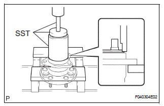
(c) Using SST and a press, install the skid control sensor to the axle hub.
SST 09214-76011
NOTICE:
- Do not tap the skid control sensor with a hammer directly.
- Check that there is no foreign matter on the skid control sensor detection portion.
- Press in the skid control sensor straight and slowly.
2. INSTALL REAR AXLE HUB & BEARING ASSEMBLY LH (See page AH-17)
3. INSTALL REAR BRAKE DRUM SUB-ASSEMBLY (for Drum Type)
(a) Aligning the matchmarks, install the rear brake drum sub-assembly.
4. INSTALL REAR DISC (for Disc Type)
(a) Aligning the matchmarks, install the rear disc.
5. INSTALL REAR DISC BRAKE CALIPER ASSEMBLY LH (for Disc Type)
(a) Install the rear disc brake caliper assembly LH with the 2 bolts.
6. SKID CONTROL SENSOR WIRE
(a) Connect the connector to the skid control sensor connector.
7. INSTALL REAR WHEEL
8. INSPECT AND ADJUST REAR WHEEL ALIGNMENT
HINT: See page SP-9.
9. CHECK ABS SPEED SENSOR SIGNAL
HINT: See page BC-10.
 Inspection
1. INSPECT REAR SPEED SENSOR
(a) Disconnect the skid control sensor connector.
(b) Measure the resistance between terminals 1 and 2
of the skid control sensor connector.
OK:
Resistance:
le ...
 Rear speed sensor (for 4wd)
Components
...
Other materials:
How to proceed with
troubleshooting
1 VEHICLE BROUGHT TO WORKSHOP
2 CUSTOMER PROBLEM ANALYSIS
Interview the customer and confirm the trouble.
Confirm the problem by duplicating the conditions
described by the customer
3 BASIC INSPECTION
Basic inspection.
Measure the battery voltage.
Standard voltage:
11 ...
Engine coolant
The coolant level is satisfactory if it is between the “FULL” and “LOW”
lines on the reservoir when the engine is cold.
Reservoir cap
“FULL” line
“LOW” line
If the level is on or below the
“LOW” line, add coolant up to the
“FULL” line.
Coolant selection
On ...
Installing the spare tire
Remove any dirt or foreign matter
from the wheel contact surface.
If foreign matter is on the wheel
contact surface, the wheel nuts
may loosen while the vehicle is in
motion, causing the tire to come
off.
Install the tire and loosely
tighten each wheel nut by hand
by ...