Toyota Sienna Service Manual: Installation
1. INSTALL SPIRAL CABLE
- Check that the front wheels are facing straight ahead.
- Set the turn signal switch to the neutral position.
NOTICE: If it is not in the neutral position, the pin of the turn signal switch may snap.
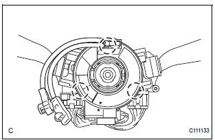
- Install the spiral cable.
NOTICE: When replacing the spiral cable with a new one, remove the lock pin before installing the steering wheel assembly.
- Connect the connectors to the spiral cable.
NOTICE: When handling the airbag connector, take care not to damage the airbag wire harness.
2. INSTALL STEERING COLUMN COVER

- Install the steering column cover with the 2 screws.
3. ADJUST SPIRAL CABLE
- Check that the ignition switch is off.
- Check that the battery negative (-) terminal is disconnected.
CAUTION: After removing the terminal, wait for at least 90 seconds before starting the operation.

- Rotate the spiral cable counterclockwise slowly by hand until it feels firm.
NOTICE: Do not turn the spiral cable by the airbag wire harness.

- Rotate the spiral cable clockwise approximately 2.5 turns to align the marks.
NOTICE: Do not turn the spiral cable by the airbag wire harness. HINT: The spiral cable will rotate approximately 2.5 turns to both the left and right from the center.
4. INSTALL STEERING WHEEL ASSEMBLY
5. INSPECT STEERING WHEEL CENTER POINT
6. INSTALL STEERING PAD
7. INSTALL STEERING WHEEL NO.2 COVER LOWER (25)
8. INSTALL STEERING WHEEL NO.3 COVER LOWER (25)
9. CONNECT CABLE TO NEGATIVE BATTERY TERMINAL
10. INSPECT STEERING PAD (25)
11. PERFORM INITIALIZATION
- Perform initialization.
HINT: Some systems need initialization when disconnecting the cable from the negative battery terminal.
12. INSPECT SRS WARNING LIGHT
- Inspect the SRS warning light
 Removal
1. PRECAUTION
CAUTION: Be sure to read "PRECAUTION" thoroughly before
servicing.
2. DISCONNECT CABLE FROM NEGATIVE BATTERY
TERMINAL
CAUTION:
Wait for 90 seconds after disconnecting th ...
 Front passenger airbag assembly
COMPONENTS
...
Other materials:
Driving in vehicle-to-vehicle distance control mode
This mode employs a radar sensor to detect the presence of vehicles
up to approximately 400 ft. (120 m) ahead, determines the current
vehicle-to-vehicle following distance, and operates to maintain a suitable
following distance from the vehicle ahead.
Note that vehicle-to-vehicle distance will ...
Door pockets
Front
Rear
NOTICE
Rear: Make sure magazines are not bent
or protruding from the sliding door pockets.
Do not insert anything too big so that
the shape of the sliding door pockets is
distorted. Such objects may obstruct the
opening/closing of the sliding ...
Manual shifting test
1. Perform manual shifting test
Hint:
With this test, it can be determined whether the
trouble occurs in the electrical circuit or is a
mechanical problem in the transaxle.
If any abnormalities are found in the following test, the
problem is in the transaxle itself.
(A) disconnec ...