Toyota Sienna Service Manual: Installation
1. INSTALL AIR FUEL RATIO SENSOR (for Bank 2 Sensor 1)

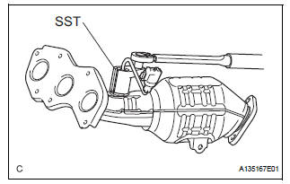
(a) Using SST, install the sensor to the exhaust manifold LH.
SST 09224-00010
Torque: 40 N*m (408 kgf*cm, 30 ft.*lbf) for use with SST 44 N*m (449 kgf*cm, 32 ft.*lbf) for use without SST
HINT:
- Use a torque wrench with a fulcrum length of 30 cm (11.81 in.).
- Make sure that SST and wrench are connected in a straight line.
(b) Connect the sensor connector.
2. INSTALL AIR FUEL RATIO SENSOR (for Bank 1 Sensor 1)
(a) Using SST, install the sensor to the exhaust manifold RH.
SST 09224-00010
Torque: 40 N*m (408 kgf*cm, 30 ft.*lbf) for use with SST 44 N*m (449 kgf*cm, 32 ft.*lbf) for use without SST
HINT:
- Use a torque wrench with a fulcrum length of 30 cm (11.81 in.).
- Make sure that SST and wrench are connected in a straight line.
3. INSTALL EXHAUST MANIFOLD RH

(a) Install the exhaust manifold RH with a new gasket and 6 nuts.
Torque: 21 N*m (214 kgf*cm, 15 ft.*lbf)

4. INSTALL CENTER EXHAUST PIPE ASSEMBLY

(a) Check compression springs.
(1) Check the compression springs using vernier calipers.
Specified length: 38.86 mm (1.5299 in.)
HINT:
If the result is not as specified, replace the compression spring.

(b) Install the gasket.
(1) Install a new gasket by hand onto the front exhaust pipe assembly.
(2) Using a plastic hammer and wooden block, tap in the new gasket until its surface is flush with the front exhaust pipe.
NOTICE:
|
(c) Install 2 new gaskets to the front exhaust pipe assembly.

(d) Install the front exhaust pipe assembly with the 2 nuts and 2 bolts.
Torque: Bolt 43 N*m (440 kgf*cm, 32 ft.*lbf) Nut 62 N*m (632 kgf*cm, 46 ft.*lbf)

(e) Install the center exhaust pipe assembly with the 2 compression springs and 2 bolts.
Torque: 43 N*m (438 kgf*cm, 32 ft.*lbf)
(f) Attach the clip.
(g) Connect the heated oxygen sensor (for Bank 1 Sensor 2) connector.
5. CONNECT CABLE TO NEGATIVE BATTERY TERMINAL 6. INSPECT FOR EXHAUST GAS LEAK

 Inspection
1. Inspect air fuel ratio sensor
(A) measure the resistance of the sensor.
Standard resistance
If the resistance is not as specified, replace the
sensor.
...
 Heated oxygen sensor (for 2wd)
Components
Removal
1. DISCONNECT CABLE FROM NEGATIVE BATTERY
TERMINAL
CAUTION:
Wait at least 90 seconds after disconnecting the
cable from the nagative (-) battery terminal to
...
Other materials:
Cold Start Idle Air Control System Performance
DESCRIPTION
This monitor will run when the engine is started at -10 to 50°C (14 to 122°F)
of the engine coolant
temperature. The DTC will set after the engine idling for 13 seconds (2 trip
detection logic).
The DTC is designed to monitor the idle air control at cold start. When the
...
Сamshaft timing oil control valve assembly
COMPONENTS
ON-VEHICLE INSPECTION
1. INSPECT CAMSHAFT TIMING CONTROL VALVE ASSEMBLY
(a) Connect the intelligent tester to the DLC3.
(b) Turn the ignition switch to the ON position.
(c) Start the engine and warm it up.
(d) Select the intelligent tester from the ACTIVE TEST
...
Short to GND in CAN Bus Line
DESCRIPTION
A short to GND is suspected in the CAN bus wire when the resistance between
terminals 4 (CG) and 6
(CANH), or terminals 4 (CG) and 14 (CANL) of the DLC3 is below 200 Ω.
Symptoms
Trouble Area
The resistance between terminals 6 (CANH) and 4 (CG), or ter ...