Toyota Sienna Service Manual: Installation
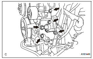
1. INSTALL WATER PUMP ASSEMBLY

(a) Install a new water pump gasket and the water pump assembly with the 16 bolts.
Torque: Bolt A 21 N*m (214 kgf*cm, 15 ft.*lbf) Bolts B and C 9.1 N*m (93 kgf*cm, 81 in.*lbf)
NOTICE:
|
2. INSTALL WATER INLET HOUSING

(a) Install a new water inlet housing No. 1 gasket and water outlet pipe O-ring.
(b) Install the water inlet housing with the 2 bolts and nut.

Torque: 10 N*m (102 kgf*cm, 7 ft.*lbf)
| NOTICE: Be careful not to allow the O-ring to get caught between the parts. |
(c) Connect the water hose.
3. INSTALL WATER PUMP PULLEY

(a) Temporarily install the water pump pulley with the 4 bolts.
(b) Using SST, hold the water pump pulley.
SST 09960-10010 (09962-01000, 09963-00700) (c) Tighten the 4 bolts.
Torque: 21 N*m (214 kgf*cm, 15 ft.*lbf)
4. INSTALL V-RIBBED BELT TENSIONER ASSEMBLY
(a) Install the V-ribbed belt tensioner assembly with the 5 bolts.
Torque: 43 N*m (438 kgf*cm, 32 ft.*lbf)
5. INSTALL NO. 2 IDLER PULLEY SUB-ASSEMBLY

(a) Install the 2 idler pulley cover plates and idler pulley sub-assemblies with the 2 bolts.
Torque: 43 N*m (438 kgf*cm, 32 ft.*lbf)
6. INSTALL NO. 1 ENGINE FRONT MOUNTING BRACKET LH (See page EM-45) 7. INSTALL GENERATOR ASSEMBLY (See page CH-26) 8. INSTALL COMPRESSOR AND MAGNETIC CLUTCH (See page AC-231) 9. INSTALL ENGINE HANGERS (See page EM-50) 10. REMOVE ENGINE STAND 11. INSTALL ENGINE ASSEMBLY WITH TRANSAXLE HINT: See page EM-44 12. ADD ENGINE COOLANT (See page CO-7) 13. INSPECT FOR COOLANT LEAK (See page CO-1)
 Inspection
1. Inspect water pump assembly
(a) Visually check the drain hole and air hole for coolant
leakage.
(b) Turn the pulley, and check that the water pump
bearing moves smoothly and noiselessly.
...
 Thermostat
Components
...
Other materials:
For front passenger side
ON-VEHICLE INSPECTION
1. INSPECT AIR MIX CONTROL SERVO MOTOR
(a) Remove the air mix control servo motor.
(b) Connect the positive (+) lead from the battery to
terminal 4 and negative (-) lead to terminal 5, then
check that the lever turns to "COOL" side smoothly.
(c) Connect ...
Reassembly
1. INSTALL CENTER CLUSTER MODULE KNOB NO.6
(for Automatic Air Conditioning System)
2. INSTALL CENTER CLUSTER MODULE KNOB NO.5
(for Automatic Air Conditioning System)
3. INSTALL CLOCK ORNAMENT
4. INSTALL PRINTED WIRE INTEGRATION BOARD
SUB-ASSEMBLY (for Automatic Air Conditioning
System)
5. IN ...
Removal
HINT:
Remove the RH side by the same procedure as the LH side.
1. REMOVE REAR WHEEL
2. DRAIN BRAKE FLUID
NOTICE:
Wash the brake fluid off immediately if it attaches to
any painted surface.
3. SEPARATE REAR BRAKE TUBE NO.4
(a) Remove the clip and a disconnect, the rear brake
flexible hos ...