Toyota Sienna Service Manual: Knock sensor
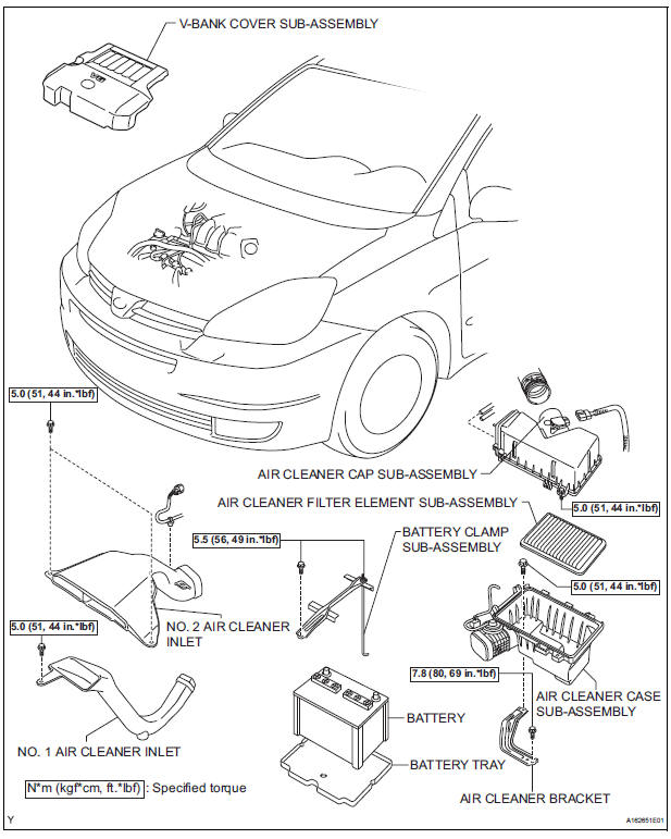
COMPONENTS


REMOVAL
1. DISCHARGE FUEL SYSTEM PRESSURE (See page FU-13) 2. REMOVE V-BANK COVER SUB-ASSEMBLY (See page EM-28) 3. DRAIN ENGINE COOLANT (See page CO-6) 4. REMOVE WINDSHIELD WIPER MOTOR ASSEMBLY HINT: (See page WW-4) 5. REMOVE FRONT OUTER COWL TOP PANEL SUBASSEMBLY (See page EM-27) 6. REMOVE AIR CLEANER CAP SUB-ASSEMBLY (See page ES-493) 7. REMOVE AIR CLEANER CASE SUB-ASSEMBLY (See page EM-28) 8. REMOVE INTAKE AIR SURGE TANK ASSEMBLY

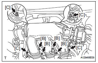
(a) Disconnect the 2 water by-pass hoses from the throttle body [A].
(b) Disconnect the vapor feed hose [B].
(c) Disconnect the throttle body connector and clamp [C].

(d) Disconnect the ventilation hose [D].
(e) Disconnect the union to check valve hose [E].

(f) Disconnect the connector [F].

(g) Using a 5 mm socket hexagon wrench, remove the 4 bolts [G].
(h) Remove the 2 nuts, 2 bolts and intake air surge tank [H].
(i) Remove the gasket from the intake air surge tank [I].
9. REMOVE FUEL MAIN TUBE SUB-ASSEMBLY (See page EM-30) 10. REMOVE INTAKE MANIFOLD (See page EM-39)
11. REMOVE KNOCK CONTROL SENSOR

(a) Disconnect the 2 knock sensor connectors.
(b) Remove the 2 bolts and then remove the 2 knock control sensors.
INSPECTION
1. KNOCK CONTROL SENSOR

(a) Using an ohmmeter, measure the resistance between the terminals.
Resistance: 120 to 280 kΩ at 20°C (68°F)
If the resistance is not specified, replace the knock control sensor.
INSTALLATION
1. INSTALL KNOCK CONTROL SENSOR

(a) Install the 2 knock control sensors with the 2 bolts as shown in the illustration.
Torque: 20 N*m (204 kgf*cm, 15 ft.*lbf) (b) Connect the 2 knock control sensor connectors.
2. INSTALL INTAKE MANIFOLD (See page EM-49) 3. INSTALL FUEL MAIN TUBE SUB-ASSEMBLY (See page EM-56) 4. INSTALL INTAKE AIR SURGE TANK
| NOTICE: DO NOT apply oil to the bolts listed below. |

(a) Install a new gasket to the intake air surge tank [A].
(b) Using a 5 mm hexagon socket wrench, install the 4 bolts [B].
Torque: 18 N*m (184 kgf*cm, 13 ft.*lbf) (c) Install the intake air surge tank with the 2 nuts and 2 bolts [C].
Torque: Nut 16 N*m (163 kgf*cm, 12 ft.*lbf) Bolt 21 N*m (214 kgf*cm, 15 ft.*lbf)

(d) Connect the connector [D].

(e) Connect the union to check valve hose [E].
(f) Connect the ventilation hose No. 2 [F].

(g) Install the clamp and connect the throttle with motor body assembly connector [G].
(h) Connect the vapor feed hose [H].
(i) Connect the 2 water by-pass hoses to the throttle with motor body assembly [I].

5. INSTALL AIR CLEANER CASE SUB-ASSEMBLY (See page EM-59) 6. INSTALL AIR CLEANER CAP SUB-ASSEMBLY (See page ES-496) 7. ADD ENGINE COOLANT (See page CO-7) 8. INSPECT FOR ENGINE COOLANT LEAK (See page CO-1) 9. INSPECT FOR FUEL LEAK (See page FU-7) 10. INSTALL FRONT OUTER COWL TOP PANEL SUBASSEMBLY (See page EM-61) 11. INSTALL WINDSHIELD WIPER MOTOR ASSEMBLY
HINT: (See page WW-5)
12. INSTALL V-BANK COVER SUB-ASSEMBLY (See page EM-63)
 Engine coolant temperature sensor
COMPONENTS
REMOVAL
1. DRAIN ENGINE COOLANT (See page CO-6)
2. REMOVE V-BANK COVER SUB-ASSEMBLY (See
page EM-28)
3. REMOVE NO. 2 AIR CLEANER INLET (See page EM-
28)
4. REMOVE NO. 1 AIR CLEAN ...
 Efi relay
INSPECTION
1. INSPECT EFI RELAY
(a) Using an ohmmeter, measure the resistance
according to the value(s) in the table below.
Standard resistance
If the result is not as specified, replace th ...
Other materials:
Short to GND in Side Squib LH Circuit
DTC B0117/45 Short to GND in Side Squib LH Circuit
DESCRIPTION
The side squib LH circuit consists of the center airbag sensor assembly and
the front seat side airbag
assembly LH.
This circuit instructs the SRS to deploy when deployment conditions are met.
DTC B0117/45 is recorded when a s ...
Maintenance data
(fuel, oil level, etc.)
Dimensions and weights
*1: Unladen vehicle
*2: The model code is indicated on the Certification Label. For details, see
“Vehicle identification” below.
*3: The towing package is required.
Toyota does not recommend towing with this vehicle without the towing
package.
Vehicle identifi ...
Brake fluid
Bleeding
HINT:
If any work is performed on the brake system or if air in the
brake lines is suspected, bleed the air out of the brake
system.
NOTICE:
Wash the brake fluid off immediately if it adheres to any
painted surfaces.
1. REMOVE COWL TOP PANEL SUB-ASSEMBLY
OUTER FRONT (See page SP-13 ...