Toyota Sienna Service Manual: Mute Signal Circuit between Radio and Navigation Assembly and Television Display Assembly
DESCRIPTION
The radio and navigation assembly controls the volume according to the MUTE signal from the television display assembly.
The MUTE signal is sent to reduce noise and a popping sound generated when switching the mode, etc.
If there is an open in the circuit, noise can be heard from the speakers when changing the sound source.
If there is a short in the circuit, even though the radio and navigation assembly is normal, no sound or only an extremely small sound can be produced.
WIRING DIAGRAM

INSPECTION PROCEDURE
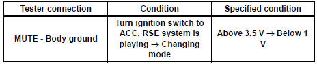
1 INSPECT TELEVISION DISPLAY ASSEMBLY

- Measure the voltage according to the value(s) in the table below.
Standard voltage
2 CHECK HARNESS AND CONNECTOR (RADIO AND NAVIGATION ASSEMBLY - TELEVISION DISPLAY ASSEMBLY)
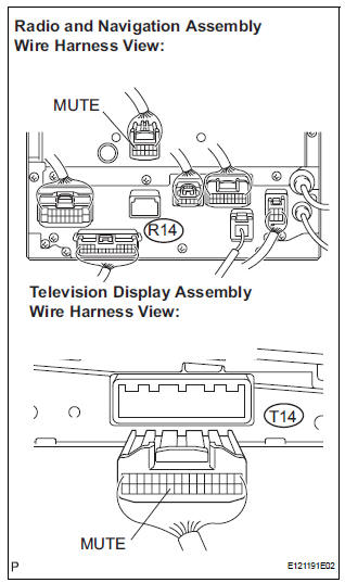
- Disconnect the radio and navigation assembly R14 connector and television display assembly T14 connector.
- Measure the resistance according to the value(s) in the table below.
Standard resistance

3 REPLACE TELEVISION DISPLAY ASSEMBLY
- Replace the television display assembly and check if it operates normally.
OK: The navigation system operates normally.
REPLACE RADIO AND NAVIGATION ASSEMBLY
 Sound Signal Circuit between Radio and Navigation Assembly and
Stereo Jack Adapter
Sound Signal Circuit between Radio and Navigation Assembly and
Stereo Jack Adapter
DESCRIPTION
The stereo jack adapter sends an external device sound signal to the radio
and navigation assembly
through this circuit.
The sound signal that has been sent is amplified by the ster ...
 Mute Signal Circuit between Radio and Navigation Assembly and
Stereo Component Amplifier
Mute Signal Circuit between Radio and Navigation Assembly and
Stereo Component Amplifier
DESCRIPTION
This circuit sends a signal to the stereo component amplifier to mute noise.
Because of that, the noise
produced by changing the sound source ceases.
If there is an open in the circ ...
Other materials:
The Rear Cross Traffic Alert function detection areas
The areas that vehicles can be detected in are outlined below.
To give the driver a more consistent time to react, the buzzer can alert
for faster vehicles from farther away.
Example:
The Rear Cross Traffic Alert function is operational when
The BSM main switch is set to on.
The ...
Stowing the spare tire
Lay down the tire with the outer
side (valve stem) facing up, and
install the holding bracket.
Turn the jack handle clockwise
to raise the tire until the tire is in
the correct position as the jack
handle skips.
Stow the tools.
The compact spare tire
The compact s ...
Inspection
1. INSPECT LOCK PLATE FOR DAMAGE
(a) Inspect the lock plate for damage.
HINT:
Reassembly of a deformed tank will be
impossible. Therefore, first correct the shape of
the lock plate groove with pliers or a similar tool,
if necessary.
Water leakage will result if the bottom of the lo ...