Toyota Sienna Service Manual: Occupant Classification Sensor Power Supply Circuit Malfunction
DTC B1793 Occupant Classification Sensor Power Supply Circuit Malfunction
DESCRIPTION
The occupant classification sensor power supply circuit consists of the occupant classification ECU and the occupant classification sensors.
DTC B1793 is recorded when a malfunction is detected in the occupant classification sensor power supply circuit.
|
DTC No. |
DTC Detecting Condition |
Trouble Area |
|
B1793 |
|
|
WIRING DIAGRAM

INSPECTION PROCEDURE
HINT:
- If troubleshooting (wire harness inspection) is difficult to perform, remove the front passenger seat installation bolts to see the under surface of the seat cushion.
- In the above case, hold the seat so that it does not fall down. Holding the seat for a long period of time may cause a problem, such as seat rail deformation. Hold the seat only as necessary.
1 CHECK DTC
- Turn the ignition switch to the ON position.
- Clear the DTCs stored in the memory.
HINT: First clear DTCs stored in the occupant classification ECU and then in the center airbag sensor assembly.
- Turn the ignition switch to the LOCK position.
- Turn the ignition switch to the ON position.
- Check the DTCs (35).
OK: DTC B1793 is not output. HINT: Codes other than DTC B1793 may be output at this time, but they are not related to this check.
2 CHECK CONNECTION OF CONNECTORS
- Turn the ignition switch to the LOCK position.
- Disconnect the negative (-) terminal cable from the battery, and wait for at least 90 seconds.
- Check that the connectors are properly connected to the occupant classification ECU and the occupant classification sensors.
OK: The connectors are properly connected
3 CHECK FRONT SEAT WIRE RH (SHORT TO B+)

- Disconnect the connectors from the occupant classification ECU and the 4 occupant classification sensors.
- Connect the negative (-) terminal cable to the battery.
- Turn the ignition switch to the ON position.
- Measure the voltage according to the value(s) in the table below.
Standard voltage

4 CHECK FRONT SEAT WIRE RH (SHORT TO GROUND)

- Turn the ignition switch to the LOCK position.
- Disconnect the negative (-) terminal cable from the battery, and wait for at least 90 seconds.
- Measure the resistance according to the value(s) in the table below.
Standard resistance

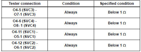
5 CHECK FRONT SEAT WIRE RH (OPEN)

- Measure the resistance according to the value(s) in the table below.
Standard resistance
6 CHECK FRONT SEAT WIRE RH (SHORT)

- Measure the resistance according to the value(s) in the table below.
Standard resistance

7 CHECK DTC
- Connect the connectors to the occupant classification ECU and the 4 occupant classification sensors.
- Connect the negative (-) terminal cable to the battery.
- Turn the ignition switch to the ON position.
- Clear the DTCs stored in the memory.
HINT: First clear DTCs stored in the occupant classification ECU and then in the center airbag sensor assembly.
- Turn the ignition switch to the LOCK position.
- Turn the ignition switch to the ON position.
- Check the DTCs (35).
OK: DTC B1793 is not output. HINT: Codes other than DTC B1793 may be output at this time, but they are not related to this check.
8 REPLACE OCCUPANT CLASSIFICATION ECU
- Turn the ignition switch to the LOCK position.
- Disconnect the negative (-) terminal cable from the battery, and wait for at least 90 seconds.
- Replace the occupant classification ECU.
HINT: Perform the inspection using parts from a normal vehicle if possible.
9 PERFORM ZERO POINT CALIBRATION
- Connect the negative (-) terminal cable to the battery.
- Connect the intelligent tester to the DLC3.
- Turn the ignition switch to the ON position.
- Using the intelligent tester, perform "Zero point
calibration" (28).
OK: "COMPLETED" is displayed
10 PERFORM SENSITIVITY CHECK
- Using the intelligent tester, perform "Sensitivity check"
(28).
Standard value: 27 to 33 kg (59.52 to 72.75 lb)
11 CHECK DTC
- Turn the ignition switch to the ON position.
- Clear the DTCs stored in the memory.
HINT: First clear DTCs stored in the occupant classification ECU and then in the center airbag sensor assembly.
- Turn the ignition switch to the LOCK position.
- Turn the ignition switch to the ON position.
- Check the DTCs (35).
OK: DTC B1793 is not output. HINT: Codes other than DTC B1793 may be output at this time, but they are related to this check
12 REPLACE FRONT SEAT ASSEMBLY RH
- Turn the ignition switch to the LOCK position.
- Disconnect the negative (-) terminal cable from the battery, and wait for at least 90 seconds.
- Replace the front seat assembly RH ( for flat type, SE-48 for manual seat, SE-58 for power seat).
13 PERFORM ZERO POINT CALIBRATION
- Connect the negative (-) terminal cable to the battery.
- Connect the intelligent tester to the DLC3.
- Turn the ignition switch to the ON position.
- Using the intelligent tester, perform "Zero point
calibration" (28).
OK: "COMPLETED" is displayed.
14 PERFORM SENSITIVITY CHECK
- Using the intelligent tester, perform "Sensitivity check"
(28).
Standard value: 27 to 33 kg (59.52 to 72.75 lb)
END
 Center Airbag Sensor Assembly Communication
Circuit Malfunction
Center Airbag Sensor Assembly Communication
Circuit Malfunction
DTC B1790 Center Airbag Sensor Assembly Communication
Circuit Malfunction
DESCRIPTION
The center airbag sensor assembly communication circuit consists of the
occupant classification ECU and
the ...
 Open in Occupant Classification ECU Battery
Positive Line
Open in Occupant Classification ECU Battery
Positive Line
DTC B1794 Open in Occupant Classification ECU Battery
Positive Line
DESCRIPTION
This circuit consists of the occupant classification ECU and the power source
circuit (battery, fuse, wire
harness ...
Other materials:
Rear view monitor
system
The rear view monitor system assists the driver by displaying an
image of the view behind the vehicle and guide lines while backing
up, for example while parking.
The screen illustrations used in this text are intended as examples,
and may differ from the image that is actually displayed on the
...
System description
1. GENERAL
This system uses ultrasonic sensors to detect any
obstacles at the corners and the rear of the vehicle.
The system then informs the driver of the distance
between the sensors and the obstacles as well as
their positions by indicating them on the clearance
sonar displ ...
Display
When the sensors detect an obstacle, the following displays inform
the driver of the position and distance to the obstacle.
Multi-information display
Front corner sensor operation
Rear corner sensor operation
Rear center sensor operation
Audio system screen
Intuitive parking ...