Toyota Sienna Service Manual: Occupant Classification System Malfunction
DTC B1150/23 Occupant Classification System Malfunction
DESCRIPTION
The occupant classification system circuit consists of the center airbag sensor assembly and the occupant classification ECU.
If the center airbag sensor assembly receives signals from the occupant classification ECU, it determines whether or not the front passenger airbag, the front seat side airbag RH, and front seat belt pretensioner RH should be operated.
DTC B1150/23 is recorded when a malfunction is detected in the occupant classification system circuit.
|
DTC No. |
DTC Detecting Condition |
Trouble Area |
|
B1150/23 |
|
|
WIRING DIAGRAM

INSPECTION PROCEDURE
1 CHECK DTC (OCCUPANT CLASSIFICATION ECU)
- Turn the ignition switch to the ON position, and wait for at least 10 seconds.
- Using the intelligent tester, check the DTCs of the occupant classification ECU (35).
OK: DTC is not output.
 GO TO INSPECTION PROCEDURE
OF DTC
OUTPUT
GO TO INSPECTION PROCEDURE
OF DTC
OUTPUT

2 CHECK DTC (CENTER AIRBAG SENSOR ASSEMBLY)

- Turn the ignition switch to the ON position, and wait for at least 60 seconds.
- Clear the DTCs stored in memory (5).
- Turn the ignition switch to the LOCK position.
- Turn the ignition switch to the ON position, and wait for at least 60 seconds.
- Check the DTCs (5).
OK: DTC B1150/23 is not output. HINT: Codes other than code B1150/23 may be output at this time, but they are not related to this check.
 Go to step 3

USE SIMULATION METHOD TO CHECK
3 CHECK CONNECTION OF CONNECTORS
- Turn the ignition switch to the LOCK position.
- Disconnect the negative (-) terminal cable from the battery, and wait for at least 90 seconds.
- Check that the connectors are properly connected to the center airbag sensor assembly and the occupant classification ECU.
OK: The connectors are connected.
 CONNECT CONNECTORS

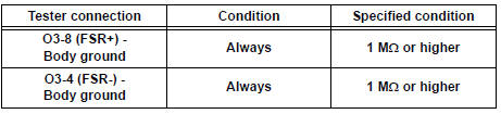
4 CHECK OCCUPANT CLASSIFICATION ECU CIRCUIT (SHORT TO GROUND)

- Disconnect the connectors from the center airbag sensor assembly and the occupant classification ECU.
- Measure the resistance according to the value(s) in the table below.
Standard resistance
 Go to step 8

5 CHECK OCCUPANT CLASSIFICATION ECU CIRCUIT (SHORT TO B+)

- Connect the negative (-) terminal cable to the battery, and wait for at least 2 seconds.
- Turn the ignition switch to the ON position.
- Measure the voltage according to the value(s) in the table below.
Standard voltage

 Go to step 9

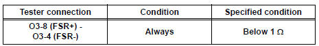
6 CHECK OCCUPANT CLASSIFICATION ECU CIRCUIT (SHORT)

- Turn the ignition switch to the LOCK position.
- Disconnect the negative (-) terminal cable from the battery, and wait for at least 90 seconds.
- Measure the resistance according to the value(s) in the table below.
Standard resistance

 Go to step 10

7 CHECK OCCUPANT CLASSIFICATION ECU CIRCUIT (OPEN)

- w/ Side airbag:
Using a service wire, connect A22-1 (FSR+) and A22-2
(FSR-) of connector "B".
NOTICE: Do not forcibly insert a service wire into the terminals of the connector when connecting.
- w/o Side airbag:
Using a service wire, connect A22-3 (FSR+) and A22-10
(FSR-) of connector "B".
NOTICE: Do not forcibly insert a service wire into the terminals of the connector when connecting.
- Measure the resistance according to the value(s) in the table below.
Standard resistance

 Go to step 11

CHECK FRONT SEAT WIRE RH (SHORT TO GROUND)

- Disconnect the front seat wire RH connector from the floor wire No. 2.
- Measure the resistance according to the value(s) in the table below.
Standard resistance

 REPAIR OR REPLACE FRONT SEAT
WIRE
RH
REPAIR OR REPLACE FRONT SEAT
WIRE
RH

REPAIR OR REPLACE FLOOR WIRE NO.2
9 CHECK FRONT SEAT WIRE RH (SHORT TO B+)

- Turn the ignition switch to the LOCK position.
- Disconnect the negative (-) terminal cable from the battery, and wait for at least 90 seconds.
- Disconnect the front seat wire RH connector from the floor wire No. 2.
- Connect the negative (-) terminal cable to the battery, and wait for at least 2 seconds.
- Turn the ignition switch to the ON position.
- Measure the voltage according to the value(s) in the table below.
Standard voltage

 REPAIR OR REPLACE FRONT SEAT
WIRE
RH
REPAIR OR REPLACE FRONT SEAT
WIRE
RH

REPAIR OR REPLACE FLOOR WIRE NO.2
10 CHECK FRONT SEAT WIRE RH (SHORT)

- Disconnect the front seat wire RH connector from the floor wire No. 2.
- Measure the resistance according to the value(s) in the table below.
Standard resistance

 REPAIR OR REPLACE FRONT SEAT
WIRE
RH
REPAIR OR REPLACE FRONT SEAT
WIRE
RH

REPAIR OR REPLACE FLOOR WIRE NO.2
11 CHECK FRONT SEAT WIRE RH (OPEN)

- Disconnect the service wire from connector "B".
- Disconnect the front seat wire RH connector from the floor wire No. 2.
- w/ Power seat:
Using a service wire, connect BO1-3 (FSR+) and BO1-5
(FSR-) of connector "D".
NOTICE: Do not forcibly insert a service wire into the terminals of the connector when connecting.
- w/o Power seat:
Using a service wire, connect BM1-3 (FSR+) and BM1-2
(FSR-) of connector "D".
NOTICE: Do not forcibly insert a service wire into the terminals of the connector when connecting.
- Measure the resistance according to the value(s) in the table below.
Standard resistance
 REPAIR OR REPLACE FRONT SEAT
WIRE
RH
REPAIR OR REPLACE FRONT SEAT
WIRE
RH

REPAIR OR REPLACE FLOOR WIRE NO.2
 Front Airbag Sensor LH Circuit Malfunction
DTC B1149/37 Front Airbag Sensor LH Circuit Malfunction
DESCRIPTION
The front airbag sensor LH circuit consists of the center airbag sensor
assembly and front airbag sensor
LH.
If the center a ...
 Passenger Airbag ON/OFF Indicator Circuit
Malfunction
Passenger Airbag ON/OFF Indicator Circuit
Malfunction
DTC B1152/28 Passenger Airbag ON/OFF Indicator Circuit
Malfunction
DESCRIPTION
The passenger airbag ON/OFF indicator circuit consists of the center airbag
sensor assembly and
passenger airbag ON ...
Other materials:
General information
A large number of ECU controlled systems are used in the
SIENNA. In general, ECU controlled systems are considered
to be very intricate, requiring a high level of technical
knowledge to troubleshoot. However, most problem checking
procedures only involve inspecting the ECU controlled
system's c ...
Fail-safe chart
HINT:
If the following conditions are detected while the cruise
control is in operation, the system clears the stored vehicle
speed in the ECM and cancels the cruise control operation.
Vehicle Condition
Auto Cancel Condition
Re-operation Condition
CRUISE main in ...
Installation
1. INSTALL TIRE PRESSURE WARNING ECU
(a) Connect the connector to the tire pressure warning
ECU.
(b) Install the tire pressure warning ECU with the screw.
2. INSTALL INSTRUMENT PANEL SAFETY PAD SUBASSEMBLY
HINT:
Refer to the instructions for INSTALLATION of the
instrument panel safety ...