Toyota Sienna Service Manual: Open or Short Circuit in ABS Motor Relay Circuit

DESCRIPTION
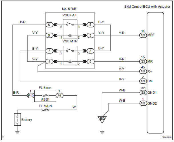
The ABS motor relay supplies power to the ABS pump motor. While the ABS & TRAC & VSC are activated, the ECU switches the ABS motor relay ON and operates the ABS pump motor.

WIRING DIAGRAM
INSPECTION PROCEDURE
1 PERFORM ACTIVE TEST USING INTELLIGENT TESTER (ABS MOTOR RELAY)
(a) Connect the intelligent tester to the DLC3.
(b) Start the engine.
(c) Select the ACTIVE TEST mode on the intelligent tester.
ABS / VSC: 
(d) Check the operation sound of the ABS motor individually when operating it with the intelligent tester.
OK: Operation sound of the ABS motor should be heard.


REPLACE BRAKE ACTUATOR ASSEMBLY
2 INSPECT NO. 5 RELAY BLOCK (POWER SOURCE TERMINAL)

(a) Remove the VSC MTR relay from the No. 5 R/B.
(b) Turn the ignition switch to the ON position.
(c) Measure the voltage according to the value(s) in the table below.
Standard voltage 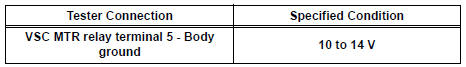


3 INSPECT ABS MOTOR RELAY (VSC MTR)

(a) Measure the resistance according to the value(s) in the table below.
Standard resistance 
(b) Apply battery positive voltage between terminals 1 and 2.
(c) Measure the resistance according to the value(s) in the table below.
Standard resistance 


4 CHECK HARNESS AND CONNECTOR (ABS MOTOR RELAY - SKID CONTROL ECU)
(a) Check for open or short circuit in harness and connector between the ABS motor relay and skid control ECU.


5 RECONFIRM DTC
(a) Clear the DTCs.
(b) Drive the vehicle at a speed of 6 km/h (4 mph) or more.
(c) Check if the same DTCs are recorded (See page BC- 82).
Result
HINT:
- The skid control ECU inspects the motor relay circuit when the stop light switch is turned off and the vehicle is running at a speed of 6 km/h (4mph) or more.
- It is suspect that the DTCs output was caused by the poor connection of the connector terminal.


REPLACE BRAKE ACTUATOR ASSEMBLY
6 INSPECT ABS 1 FUSE
(a) Remove the ABS 1 fuse from the FL block.
(b) Measure the resistance according to the value(s) in the table below.
Standard resistance 


7 INSPECT ABS MOTOR RELAY (VSC FAIL)

(a) Measure the resistance according to the value(s) in the table below.
Standard resistance 
(b) Apply battery positive voltage between terminals 1 and 2.
(c) Measure the resistance according to the value(s) in the table below.
Standard resistance 


REPAIR OR REPLACE HARNESS OR CONNECTOR
REPAIR OR REPLACE HARNESS OR CONNECTOR
 SFR Solenoid Circuit
DESCRIPTION
This solenoid goes on when signals are received from the ECU and controls the
pressure acting on the
wheel cylinders to control the braking force.
WIRING DIAGRAM
INSPECTI ...
 Open or Short Circuit in ABS Solenoid Relay Circuit
DESCRIPTION
The ABS solenoid relay is built in the brake actuator assembly. This relay
supplies power to each ABS
solenoid. If the initial check is OK, after the ignition switch is turned to t ...
Other materials:
Open in Rear Curtain Shield Squib LH Circuit
DTC B1636/88 Open in Rear Curtain Shield Squib LH Circuit
DESCRIPTION
The rear curtain shield squib LH circuit consists of the center airbag sensor
assembly and the curtain
shield airbag assembly LH.
The circuit instructs the SRS to deploy when deployment conditions are met.
DTC B1636/88 ...
Driving tips
Winter driving tips
Carry out the necessary preparations and inspections before
driving the vehicle in winter. Always drive the vehicle in a manner
appropriate to the prevailing weather conditions.
Preparation for winter
Use fluids that are appropriate to the prevailing outside temperatures. ...
Front Airbag Sensor RH Circuit Malfunction
DTC B1148/36 Front Airbag Sensor RH Circuit Malfunction
DESCRIPTION
The front airbag sensor RH circuit consists of the center airbag sensor
assembly and front airbag sensor
RH. If the center airbag sensor assembly receives signals from the front airbag
sensor RH, it judges
whether or not the ...