Toyota Sienna Service Manual: Operating Light Control Rheostat does not Change Light Brightness
DESCRIPTION
The meter CPU receives signals for adjusting illumination on the meter from this circuit. The meter CPU detects the illumination level selected by the user according to the position of the rheostat knob.
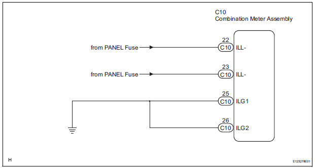
WIRING DIAGRAM
INSPECTION PROCEDURE
1 READ VALUE OF INTELLIGENT TESTER (LIGHT RHEOSTAT)
- Connect the intelligent tester to the DLC3.
- Turn the switch to the ON position.
- Turn the tester ON.
- Enter the following menus: DIAGNOSIS / OBD/MOBD / METER / DATA LIST.
- Check the values by referring to the table below.
METER:

OK: Light brightness displayed on the tester is almost the same as the actual light brightness.
REPLACE COMBINATION METER ASSEMBLY
2 CHECK HARNESS AND CONNECTOR (LIGHT CONTROL RHEOSTAT CIRCUIT)
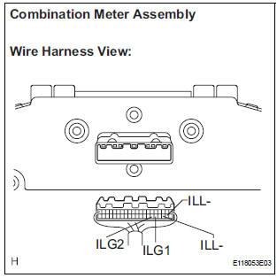
- Disconnect the C10 connectors.
- Measure the resistance according to the value(s) in the table below.
Standard resistance

- Measure the voltage according to the value(s) in the table below.
Standard voltage

REPLACE COMBINATION METER ASSEMBLY
 Driver Side Seat Belt Warning Light does not Operate
DESCRIPTION
When turning the ignition switch to the ON position, the combination meter
assembly communicates with
the supplemental restraint system by the multiplex communication system. Unless
...
 Meter Illumination is Always Dark
DESCRIPTION
Confirm that the vehicle is equipped with the optitron meter, then
check this circuit.
The combination meter assembly receives a auto dimmer signal from the
body ECU by t ...
Other materials:
Dtc check / clear
1. DTC CHECK (USING SST CHECK WIRE)
(a) Check DTCs.
(1) Turn the ignition switch off.
(2) Using SST, connect terminals TC and CG of
DLC3.
SST 09843-18040
(3) Turn the ignition switch to the ON position.
(4) Read and record any DTCs from the tire
pressure warning light on the combin ...
Adjustment
HINT:
If the malfunction does not disappear by following the
procedure in ADJUSTMENT and the rear No. 2 seat
assembly needs to be replaced, do not disassemble the rear
No. 2 seat assembly.
1. ADJUST FRONT LEG
HINT:
Perform the following procedure if the inner leg does not
lock.
P ...
Illumination for Panel Switch does not Come on with Tail Switch ON
INSPECTION PROCEDURE
1 CHECK VEHICLE SIGNAL (DISPLAY CHECK MODE)
Enter the "Display Check" mode (Vehicle Signal Check Mode).
Check that the display changes between ON and OFF
according to the light control switch operation.
OK
HINT:
This display is updated once ...