Toyota Sienna Service Manual: Rear Room Temperature Sensor Circuit
DESCRIPTION
This sensor detects the rear cabin temperature that is used as the basis for
temperature control and
sends a signal to the A/C amplifier.
WIRING DIAGRAM

INSPECTION PROCEDURE
1 READ VALUE OF INTELLIGENT TESTER
(a) Connect the intelligent tester to the DLC3.
(b) Turn the ignition switch to the ON position and turn the intelligent tester main switch on.
(c) Select the item below in the DATA LIST, and read the display on the intelligent tester.
DATA LIST / AIR CONDITIONER: 
OK: The display is as specified in the normal condition column.
Result 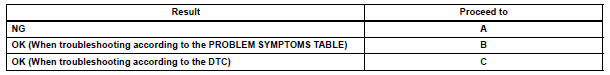


2 INSPECT REAR A/C ROOM TEMPERATURE SENSOR

(a) Remove the rear A/C room temperature sensor.
(b) Measure the resistance according to the value(s) in the table below.
Standard resistance 
NOTICE:
- Hold the sensor only by its connector. Touching the sensor may change the resistance value.
- When measuring, the sensor temperature must be the same as the rear cabin temperature.
HINT: As the temperature increases, the resistance decreases (see the graph).


3 CHECK HARNESS AND CONNECTOR (REAR A/C ROOM TEMPERATURE SENSOR - A/C AMPLIFIER)

(a) Disconnect the connector from the A/C amplifier.

(b) Disconnect the connector from the rear A/C room temperature sensor.
(c) Measure the resistance according to the value(s) in the table below.
Standard resistance 


REPLACE A/C AMPLIFIER
 Rear evaporator temperature sensor circuit
DESCRIPTION
The rear evaporator temperature sensor is installed on the rear evaporator.
It detects the rear evaporator
temperature. The sensor sends a signal to the A/C amplifier. The resistance o ...
 Solar Sensor Circuit (Passenger Side)
DTC B1421/21 Solar Sensor Circuit (Passenger Side)
DESCRIPTION
The solar sensor, which is installed on the upper side of the instrument
panel, detects sunlight and
controls the air conditioni ...
Other materials:
Short to GND in Front Pretensioner Squib RH
Circuit
DTC B0132/61 Short to GND in Front Pretensioner Squib RH
Circuit
DESCRIPTION
The front pretensioner squib RH circuit consists of the center airbag sensor
assembly and the front seat
outer belt assembly RH.
This circuit instructs the SRS to deploy when deployment conditions are met.
DTC B ...
Open in Side Squib RH Circuit
DTC B0111/44 Open in Side Squib RH Circuit
DESCRIPTION
The side squib RH circuit consists of the center airbag sensor assembly and
the front seat side airbag
assembly RH.
The circuit instructs the SRS to deploy when deployment conditions are met.
DTC B0111/44 is recorded when an open circ ...
DTC check / clear
1. CHECK DTC (USING INTELLIGENT TESTER)
Checking DTCs.
Connect the intelligent tester to the DLC3.
Turn the ignition switch ON.
Read DTCs by following the prompts on the
tester screen.
HINT:
Refer to the intelligent tester operator's manual
for furthe ...