Toyota Sienna Service Manual: Reassembly
1. INSTALL REAR DOOR WIRE SUB-ASSEMBLY LH

- Install the wire.
NOTICE: When installing the wire, push the areas where the clips are installed in order to prevent damage and deformation.
- Install the 2 screws.
2. INSTALL REAR DOOR LOCK ASSEMBLY LH
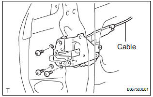
- Apply MP grease to the sliding and rotating areas of the lock.
- Apply adhesive to the threads of the screws.
Adhesive: Part No. 08833-00070, THREE BOND 1324 or equivalent
- Install the lock to the door panel with the 3 screws.
Torque: 5.0 N*m (51 kgf*cm, 44 in.*lbf)
- Connect the cable.
3. INSTALL SLIDE DOOR LOCK ASSEMBLY FRONT LH

- Apply MP grease to the sliding and rotating areas of the lock.
- Apply adhesive to the threads of the screws.
Adhesive: Part No. 08833-00070, THREE BOND 1324 or equivalent
- Install the lock front to the door panel with the 3
screws.
Torque: 5.0 N*m (51 kgf*cm, 44 in.*lbf)
- Connect the 2 cables.
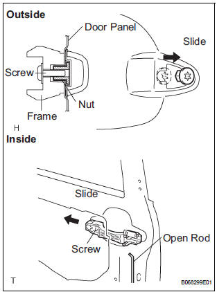
4. INSTALL REAR DOOR OUTSIDE HANDLE FRAME SUB-ASSEMBLY LH
- Apply MP grease to the sliding and rotating parts of the outside handle frame.
- Slide the outside handle frame in the direction indicated by the arrow mark in the illustration.
- Using a torx socket wrench (T30), install the outside
handle frame with the screw.
Torque: 7.0 N*m (71 kgf*cm, 62 in.*lbf) NOTICE: Insert a cover between the nut and the door panel.
- Install the open rod.
 Adjustment
HINT:
On the RH side, use the same procedures as on the LH side.
1. INSPECT SLIDE DOOR PANEL SUB-ASSEMBLY LH
Check that the clearance is within the standard
range.
Standard
2. ADJU ...
 Reassembly
1. INSTALL REAR DOOR WIRE SUB-ASSEMBLY LH
Install the wire.
NOTICE:
When installing the wire, push the areas where
the clips are installed in order to prevent
damage and deformation.
...
Other materials:
Reassembly
1. INSTALL DIFFERENTIAL CASE SUB-ASSEMBLY NO.2
(a) Coat the front differential side gear thrust washer
No.1, front differential planetary ring gear, front
differential pinion No.2, front differential pinion thrust
washer No.2, front differential pinion shaft holder,
front differential pinio ...
Memory recall function
Each electronic key can be registered to recall your preferred driving
position.
Registering procedure
Record your driving position to button “1” or “2” before performing
the following:
Carry only the key you want to register, and then close the driver’s
door.
If 2 or more keys ar ...
MIL Circuit
DESCRIPTION
The MIL (Malfunction Indicator Lamp) is used to indicate vehicle malfunctions
detected by the ECM.
When the ignition switch is turned to the ON position, power is supplied to the
MIL circuit, and the ECM
provides the circuit ground which illuminates the MIL.
The MIL operation ...