Toyota Sienna Service Manual: Reassembly
1. Install lower radiator tank

(a) After checking that there are no foreign objects in the lock plate groove, install a new O-ring without twisting it.
HINT: When cleaning the lock plate groove, lightly rub it with sandpaper without scratching it.

(b) Tap the lock plate with a plastic-faced hammer so that there is no gap between the lock plate and the tank.
| NOTICE: Do not tap the areas protruding around the pipes, brackets or tank ribs. |

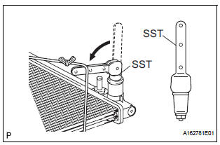
(c) Install the punch assembly to the overhaul handle, inserting it in the hole in part A as shown in the illustration.
SST 09230-01010 (09231-01010, 09231-01020), 09231-14010
(d) While gripping the handle, adjust the stopper bolt so that dimension B is as specified below.
Dimension B: 8.8 mm (0.347 in.)

(e) Lightly press SST against the lock plate in the order shown in the illustration. After repeating this procedure a few times, fully crimp the lock plate by squeezing the handle until stopped by the stopper bolt.
SST 09230-01010 (09231-01010, 09231-01020), 09231-14010

NOTICE:
|

(f) Check the lock plate height A after completing the crimping.

Standard plate height A: 8.8 mm (0.347 in.)
If the height is not as specified, readjust the stopper bolt of the handle and crimp the lock plate again.
2. INSTALL UPPER RADIATOR TANK
HINT: The installation procedure for the upper radiator tank is the same as that for the lower radiator tank.
3. INSTALL DRAIN PLUG
(a) Install a new O-ring to the drain plug.
(b) Install a new O-ring to the air drain plug.
(c) Install the drain plug and air drain plug.
4. INSPECT FOR WATER LEAK
(a) Plug the inlet and outlet pipes of the radiator with SST.
SST 09230-01010 (09231-00030, 09231-00060) (b) Using a radiator cap tester, apply pressure to the radiator.
Standard test pressure: 177 kPa (1.8 kgf/cm2, 26 psi) (c) Submerge the radiator in water.
(d) Inspect for leak.

HINT: On radiators with resin tanks, there is clearance between the tank and lock plate where a minute amount of air will remain, giving the appearance of an air leak when the radiator is submerged in water.
Therefore, before doing the water leak test, first swish the radiator around in the water until all air bubbles disappear.
5. INSTALL RADIATOR WATER INLET

(a) Install the radiator water inlet with the 2 bolts.
Torque: 7.1 N*m (72 kgf*cm, 63 in.*lbf)
 Inspection
1. INSPECT LOCK PLATE FOR DAMAGE
(a) Inspect the lock plate for damage.
HINT:
Reassembly of a deformed tank will be
impossible. Therefore, first correct the shape of
the lock plate groov ...
 Installation
1. Connect inlet sub-assembly
(a) Connect the inlet hose to the radiator.
(b) Install the inlet sub-assembly to the radiator with the
bolt.
Torque: 7.1 N*m (72 kgf*cm, 63 in.*lbf)V
2. Ins ...
Other materials:
Short to GND in Front Pretensioner Squib RH
Circuit
DTC B0132/61 Short to GND in Front Pretensioner Squib RH
Circuit
DESCRIPTION
The front pretensioner squib RH circuit consists of the center airbag sensor
assembly and the front seat
outer belt assembly RH.
This circuit instructs the SRS to deploy when deployment conditions are met.
DTC B ...
Horn
To sound the horn, press on or
close to the mark.
WARNINGCaution while driving
Do not adjust the steering wheel while driving.
Doing so may cause the driver to mishandle the vehicle and cause an
accident,
resulting in death or serious injury.
After adjusting the steeri ...
Door control transmitter
INSPECTION
1. INSPECT DOOR CONTROL TRANSMITTER
Inspect operation of the transmitter.
Remove the battery (lithium battery) from the transmitter.
Install a new or normal battery (lithium battery).
When a new or normal battery is not available,
connect 2 new ...