Toyota Sienna Service Manual: Refrigerant
On-vehicle inspection
1. INSPECT REFRIGERANT PRESSURE WITH MANIFOLD GAUGE SET
(a) This method uses a manifold gauge set to locate problem areas. Read the manifold gauge pressure when these conditions are established.
Test conditions:
- Temperature at the air inlet is 30 to 35°C (86 to 95°F).
- Engine is running at 1,500 rpm.
- All doors are fully open.
- Blower speed control switch is at HI.
- Temperature control switch is at MAX. COOL.
- A/C switch is ON.
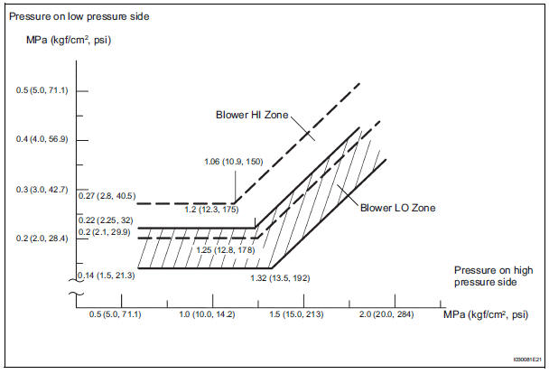
(b) Gauge readings (Reference)


(1) Normally functioning refrigeration system
Gauge reading 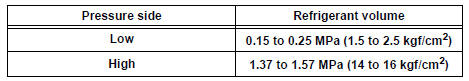
(2) The A/C system periodically changes between normal and improper function due to moisture in the refrigerant system.

(3) The A/C system does not function effectively due to insufficient cooling.

(4) The A/C system does not function effectively due to poor circulation of the refrigerant.

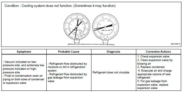
(5) The A/C system does not function intermittently because the refrigerant does not circulate.
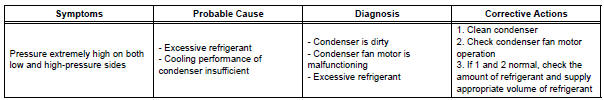
(6) The A/C system does not function effectively due to overcharged refrigerant or insufficient cooling of the condenser.

(7) The A/C system does not function due to air in the refrigeration system.
| CAUTION: The low-pressure piping may be very hot and cause serious burns. |

(8) The A/C system does not function effectively due to an expansion valve malfunction.

(9) The A/C system does not function due to a defective compressor.

Gauge readings (Reference)
 Terminals of ecu
1. A/C AMPLIFIER
HINT:
Check from the rear of the connector while it is
connected to the A/C amplifier.
(a) Waveform 1:
(b) Waveform 2: ...
 Replacement
1. DISCHARGE REFRIGERANT FROM
REFRIGERATION SYSTEM
SST 07110-58060 (07117-58080, 07117-58090,
07117-78050, 07117-88060, 07117-88070,
07117-88080)
(a) Turn the A/C switch to ON.
(b) Operating t ...
Other materials:
Unlocking and locking the doors from the outside
Entry function (vehicles with a smart key system)
Carry the electronic key to enable this function.
Grip the driver’s door handle
to unlock the door. Grip the
passenger’s door handle to
unlock all the doors.*
Make sure to touch the sensor
on the back of the handle.
The doors ...
If a warning light turns on
or a warning buzzer
sounds
Calmly perform the following actions if any of the warning lights
comes on or flashes. If a light comes on or flashes, but then
goes off, this does not necessarily indicate a malfunction in the
system. However, if this continues to occur, have the vehicle
inspected by your Toyota dealer.
Warnin ...
Installation
1. INSTALL NO. 2 REAR SEAT OUTER BELT ASSEMBLY
NOTICE:
Do not disassemble the retractor.
Check the degree of tilt when the No. 2 rear seat
outer belt assembly begins to lock the ELR.
Check that the belt does not lock within 15 of
tilt in all directions but that the be ...