Toyota Sienna Service Manual: Removal
1. Remove windshield wiper motor assembly hint: (see page ww-4) 2. Remove front outer cowl top panel subassembly (see page em-27) 3. Drain engine coolant (see page co-6) 4. Remove v-bank cover sub-assembly (see page em-28) 5. Remove no. 2 Air cleaner inlet (see page em- 28) 6. Remove no. 1 Air cleaner inlet (see page em- 28) 7. Remove air cleaner cap sub-assembly
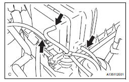
(A) disconnect the 3 vacuum hoses.

(b) Remove the No. 2 ventilation hose and air cleaner hose band.
(c) Disconnect the vacuum hose (EVAP) from the air cleaner hose.
(d) Disconnect the mass air flow meter connector.
(e) Remove the 2 bolts and air cleaner cap subassembly.
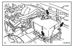
8. REMOVE AIR CLEANER CASE SUB-ASSEMBLY (See page EM-28)
9. REMOVE THROTTLE BODY

(a) Disconnect the throttle body connector and clamp.

(b) Disconnect the 2 water by-pass hoses from the throttle body.

(c) Remove the 4 bolts and throttle body.
(d) Remove the throttle body gasket from the intake air surge tank.
INSPECTION
1. INSPECT THROTTLE BODY

(a) Using an ohmmeter, measure the resistance between the terminals.
Standard resistance

If the result is not as specified, replace the throttle body assembly.
 On-vehicle inspection
1. INSPECT THROTTLE BODY
(a) Listen to the throttle control motor operating sounds.
(1) Turn the ignition switch to the ON position.
(2) When pressing the accelerator pedal position
sensor lever ...
 Installation
1. INSTALL THROTTLE BODY
(a) Install a new throttle body gasket to the intake air
surge tank.
(b) Install the throttle body with the 4 bolts.
Torque: 10 N*m (102 kgf*cm, 7 ft.*lbf)
...
Other materials:
Precaution
1. INSPECTION PROCEDURE FOR VEHICLE INVOLVED
IN ACCIDENT
Perform the zero point calibration and sensitivity
check if any of the following conditions occur.
The occupant classification ECU is replaced.
Accessories (seatback tray and seat cover, etc.)
are installed.
...
Removal
1. REMOVE GLOVE COMPARTMENT DOOR ASSEMBLY
Push the right side wall and then push the left wall
to release the stoppers.
Pull the glove compartment door sub-assembly
rearward to remove it.
2. REMOVE NO. 2 INSTRUMENT PANEL BOX
Disengage the 2 claws and 4 cl ...
TC and CG Terminal Circuit
DESCRIPTION
DTC output mode is set by connecting terminals 13 (TC) and 4 (CG) of the
DLC3. The DTCs are indicated
by blinks of the tire pressure warning light.
WIRING DIAGRAM
HINT:
When each warning light blinks continuously, a ground short in the wiring of
terminal TC of the DLC3 or an ...