Toyota Sienna Service Manual: Removal
1. Disconnect cable from negative battery terminal
2. REMOVE STEERING COLUMN COVER LOWER

(A) insert the key into the ignition key cylinder and release the steering lock.
(B) turn the steering wheel clockwise to gain access to the screw and remove the screw.

(c) Turn the steering wheel counterclockwise to gain access to the screw and remove the screw.
(d) Detach the 4 claws, and remove the steering column cover lower.
3. REMOVE IGNITION SWITCH ASSEMBLY
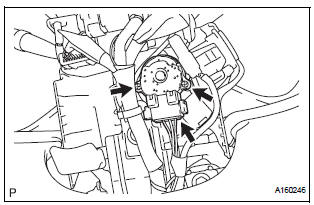
(a) Disconnect the ignition switch connector.
(b) Remove the 2 screws and ignition switch.
 Ignition switch
Components
...
 Inspection
1. Inspect ignition switch assembly
(a) Measure the resistance of the switch.
Standard resistance
If the result is not as specified, replace the switch
assembly. ...
Other materials:
Park / Neutral Position Switch Circuit
DESCRIPTION
The fold seat control ECU receives signals from the Park/Neutral position
switch and controls the seat
stowing and return operations. If the shift lever is in any position other than
P the seat cannot be operated.
If the ignition switch is in ACC or IG the seat cannot be operate ...
Perform monitor drive pattern
The monitor results and test values can be checked with
the OBD II scan tool or the intelligent tester. The engine
control module (ECM) monitors the emissions-related
components such as the thermostat, catalyst converter
and evaporative emissions (EVAP), and determines
whether they are function ...
Open in Driver Side Squib 2nd Step Circuit
DTC B1181/18 Open in Driver Side Squib 2nd Step Circuit
DESCRIPTION
The driver side squib 2nd step circuit consists of the center airbag sensor
assembly, the spiral cable and
the steering pad.
The circuit instructs the SRS to deploy when deployment conditions are met.
DTC B1181/18 is reco ...