Toyota Sienna Service Manual: Removal
1. REMOVE ENGINE ASSEMBLY WITH TRANSAXLE
HINT: (See page EM-26)
2. REMOVE FRONT DRIVE SHAFT ASSEMBLY LH
HINT: (See page DS-6)
3. REMOVE FRONT DRIVE SHAFT ASSEMBLY RH
HINT: (See page DS-6)
4. REMOVE TRANSMISSION CONTROL CABLE CLAMP
(a) Remove the bolt and the transmission control cable clamp.

5. REMOVE WIRE HARNESS CLAMP

(a) Disconnect the wire harnesses from the clamp.
(b) Remove the 3 bolts and 2 clamps.
6. DISCONNECT WIRE HARNESS

(a) Remove the bolt and disconnect the wire harness.
7. REMOVE STARTER ASSEMBLY

(a) Disconnect the connector (1).
(b) Remove the nut (2) and disconnect the starter wire.
(c) Remove the 2 bolts (3) and starter assembly.
8. DISCONNECT CONNECTORS
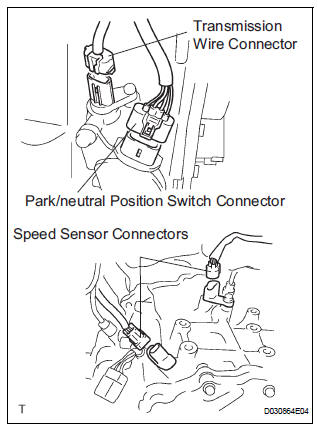
(a) Disconnect the transmission wire connector.
(b) Disconnect the park/neutral position switch connector.
(c) Disconnect the 2 speed sensor connectors.
9. REMOVE TRANSMISSION CONTROL CABLE BRACKET NO.1

(a) Remove the bolt and automatic transmission oil cooler tube clamp.
(b) Remove the 2 bolts and transmission control cable bracket No.1.
10. REMOVE TRANSMISSION OIL FILLER TUBE SUBASSEMBLY

(a) Remove the ATF level gauge.
(b) Disconnect the wire harnesses 2 clamps from the oil filler tube.
(c) Remove the 2 bolts and oil filler tube.
(d) Remove the O-ring from the oil filler tube.
11. REMOVE OIL COOLER INLET TUBE NO.1
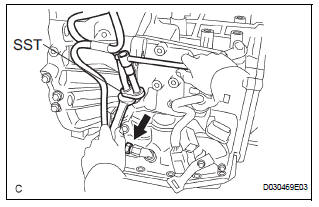
(a) Using SST and a wrench, disconnect the oil cooler inlet tube No.1.
SST 09023-12701
12. REMOVE OIL COOLER OUTLET TUBE NO.1
(a) Using SST and a wrench, disconnect the oil cooler outlet tube No.1.
SST 09023-12701
13. REMOVE ENGINE MOUNTING BRACKET FRONT

(a) Remove the 3 bolts and engine mounting bracket front.
14. REMOVE AUTOMATIC TRANSAXLE ASSEMBLY

(a) Remove the 2 bolts and flywheel housing under cover.

(b) Turn the crankshaft to gain access and remove the 6 bolts while holding the crankshaft pulley bolt with a wrench.
HINT: There will be one green colored bolt.
(c) Remove the 10 bolts.
(d) Separate and remove the automatic transaxle.
15. REMOVE TORQUE CONVERTER CLUTCH ASSEMBLY

16. INSPECT TORQUE CONVERTER CLUTCH ASSEMBLY
HINT: (See page AX-170)
 Automatic transaxle assembly
Components
...
 Installation
1. Install torque converter clutch assembly
(a) Install the torque converter clutch to the automatic
transaxle.
(b) Using vernier calipers and a straight edge, measure
the dimension "A& ...
Other materials:
Data list / active test
1. DATA LIST
HINT:
Using the intelligent tester to read the DATA LIST allows
the values or states of switches, sensor, actuators and
other items to be read without removing any parts. This
non-intrusive inspection can be very useful because
intermittent conditions or signals may be discovered
...
Noise Occurs from Generator while Engine is Running
INSPECTION PROCEDURE
1 CHECK LOOSENESS OF V-RIBBED BELT
(a) Check the tension of the belt by pushing it down with a
finger.
OK:
The tension of the belt is enough.
2 CHECK V-RIBBED BELT FOR WEAR
(a) Check the V-ribbed belt for wear.
OK:
The V-ribbed belt is not worn.
3 CHECK CLUTC ...
Installation
1. INSTALL FRONT SEAT ASSEMBLY RH
Place the seat assembly in the cabin.
NOTICE:
Be careful not to damage the body.
Connect the connectors under the seat assembly.
Tighten the 2 bolts on the front side of the seat
assembly.
Torque: 37 N*m (375 kgf*cm, 27 ft.*lbf)
...