Toyota Sienna Service Manual: Side Airbag Sensor Assembly LH Circuit Malfunction
DTC B1141/33 Side Airbag Sensor Assembly LH Circuit Malfunction
DESCRIPTION
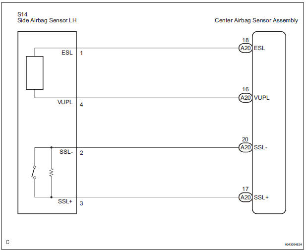
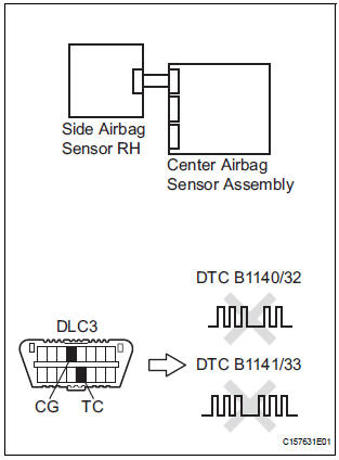
The side airbag sensor LH circuit consists of the center airbag sensor assembly and side airbag sensor LH.
If the center airbag sensor assembly receives signals from the side airbag sensor LH, it judges whether or not the SRS should be activated.
DTC B1141/33 is recorded when a malfunction in the side airbag sensor LH circuit is detected.
|
DTC No. |
DTC Detecting Condition |
Trouble Area |
|
B1141/33 |
|
|
WIRING DIAGRAM
INSPECTION PROCEDURE
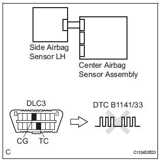
1 CHECK DTC
- Turn the ignition switch to the ON position, and wait for at least 60 seconds.
- Clear the DTCs stored in memory (5).
- Turn the ignition switch to the LOCK position.
- Turn the ignition switch to the ON position, and wait for at least 60 seconds.
- Check the DTCs (5).
OK: DTC B1141/33 is not output. HINT: Codes other than DTC B1141/33 may be output at this time, but they are not related to this check.
 Go to step 2

USE SIMULATION METHOD TO CHECK
2 CHECK CONNECTION OF CONNECTORS
- Turn the ignition switch to the LOCK position.
- Disconnect the negative (-) terminal cable from the battery, and wait for at least 90 seconds.
- Check that the connectors are properly connected to the center airbag sensor assembly and the side airbag sensor LH.
OK: The connectors are connected.
 CONNECT CONNECTORS

3 CHECK FLOOR WIRE (OPEN)
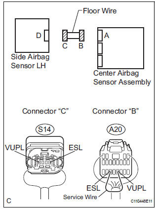
- Disconnect the connectors from the center airbag sensor assembly and the side airbag sensor LH.
- Using a service wire, connect A20-16 (VUPL) and A20-
18 (ESL) of connector "B".
NOTICE: Do not forcibly insert a service wire into the terminals of the connector when connecting.
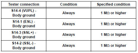
- Measure the resistance according to the value(s) in the table below.
Standard resistance

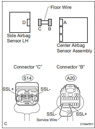
- Using a service wire, connect A20-17 (SSL+) and A20-
20 (SSL-) of connector "B".
NOTICE: Do not forcibly insert a service wire into the terminals of the connector when connecting.
- Measure the resistance according to the value(s) in the table below.
Standard resistance

 REPAIR OR REPLACE FLOOR WIRE

4 CHECK FLOOR WIRE (SHORT TO B+)

- Disconnect the service wire from connector "B".
- Connect the negative (-) terminal cable to the battery, and wait for at least 2 seconds.
- Turn the ignition switch to the ON position.
- Measure the voltage according to the value(s) in the table below.
Standard voltage

 REPAIR OR REPLACE FLOOR WIRE

5 CHECK FLOOR WIRE (SHORT TO GROUND)

- Turn the ignition switch to the LOCK position.
- Disconnect the negative (-) terminal cable from the battery, and wait for at least 90 seconds.
- Measure the resistance according to the value(s) in the table below.
Standard resistance
 REPAIR OR REPLACE FLOOR WIRE

6 CHECK FLOOR WIRE (SHORT)

- Measure the resistance according to the value(s) in the table below.
Standard resistance

 REPAIR OR REPLACE FLOOR WIRE

7 CHECK SIDE AIRBAG SENSOR LH
- Connect the connector to the center airbag sensor assembly.
- Interchange the side airbag sensor RH with LH and connect the connectors to them.
- Connect the negative (-) terminal cable to the battery, and wait for at least 2 seconds.
- Turn the ignition switch to the ON position, and wait for at least 60 seconds.
- Clear the DTCs stored in memory (5).
- Turn the ignition switch to the LOCK position.
- Turn the ignition switch to the ON position, and wait for at least 60 seconds.
- Check the DTCs (5).
Result

HINT: Codes other than DTC B1140/32 and B1141/33 may be output at this time, but they are not related to this check.
 REPLACE SIDE AIRBAG SENSOR
LH
REPLACE SIDE AIRBAG SENSOR
LH
 REPLACE CENTER AIRBAG SENSOR
ASSEMBLY
REPLACE CENTER AIRBAG SENSOR
ASSEMBLY

USE SIMULATION METHOD TO CHECK
 Side Airbag Sensor Assembly RH Circuit Malfunction
DTC B1140/32 Side Airbag Sensor Assembly RH Circuit Malfunction
DESCRIPTION
The side airbag sensor RH circuit consists of the center airbag sensor
assembly and side airbag sensor
RH.
If the ce ...
 Front Airbag Sensor RH Circuit Malfunction
DTC B1148/36 Front Airbag Sensor RH Circuit Malfunction
DESCRIPTION
The front airbag sensor RH circuit consists of the center airbag sensor
assembly and front airbag sensor
RH. If the center airb ...
Other materials:
Check for intermittent problems
1. CHECK FOR INTERMITTENT PROBLEMS
HINT:
For use of the intelligent tester only:
Inspect the vehicle's ECM using check mode.
Intermittent problems are easier to detect with an
intelligent tester when the ECM is in check mode. In
check mode, the ECM uses 1 trip detection logic, which
is more ...
Driving position memory
Your preferred driving position (the position of the driver’s seat and
outside rear view mirrors) can be recalled by pressing a button.
Two different driving positions can be recorded into memory.
Recording procedure
Check that the shift lever is in P.
Turn the engine switch to IGNI ...
If a warning light turns on
or a warning buzzer
sounds
Calmly perform the following actions if any of the warning lights
comes on or flashes. If a light comes on or flashes, but then
goes off, this does not necessarily indicate a malfunction in the
system. However, if this continues to occur, have the vehicle
inspected by your Toyota dealer.
Warnin ...