Toyota Sienna Service Manual: Skid Control Buzzer Circuit
DESCRIPTION
The skid control buzzer sounds and SLIP indicator blinking during VSC operation.
WIRING DIAGRAM

INSPECTION PROCEDURE
1 PERFORM ACTIVE TEST USING INTELLIGENT TESTER (SKID CONTROL BUZZER)
(a) Connect the intelligent tester to the DLC3.
(b) Start the engine.
(c) Select the item "VSC / BR WARN BUZ" in the ACTIVE TEST and operate the skid control buzzer on the intelligent tester.
ABS / VSC: 
(d) Check that skid control buzzer sounds by operating with the intelligent tester.
OK: The skid control buzzer sounds in accordance with operation of the intelligent tester.

REPLACE BRAKE ACTUATOR ASSEMBLY
2 INSPECT SKID CONTROL BUZZER
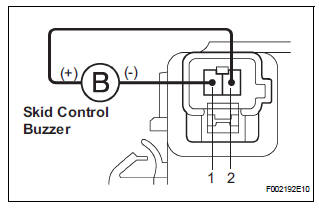
(a) Disconnect the skid control buzzer connector.
(b) Apply battery negative voltage to terminal 1, and battery positive voltage to terminal 2 of the skid control buzzer connector, and check that the buzzer sounds.
OK: The skid control buzzer sound should be heard.


3 CHECK HARNESS AND CONNECTOR (SKID CONTROL BUZZER - SKID CONTROL ECU)

(a) Disconnect the skid control buzzer connector and the skid control ECU connector.
(b) Measure the resistance according to the value(s) in the table below.
Standard resistance 
(c) Measure the resistance according to the value(s) in the table below.
Standard resistance
NOTICE: When replacing the brake actuator assembly, perform zero point calibration (See page BC-70)

REPLACE BRAKE ACTUATOR ASSEMBLY
 Slip Indicator Light does not Come ON
DESCRIPTION
The skid control ECU is connected to the combination meter via CAN and
multiplex communications.
The SLIP indicator blinks during VSC and/or TRAC operation.
When the system fails, ...
 TC and CG Terminal Circuit
DESCRIPTION
Connecting terminals TC and CG of the DLC3 causes the ECU to display the DTC
by blinking the ABS
warning light and/or VSC warning light.
WIRING DIAGRAM
INSPECTION PROCEDURE
NOTI ...
Other materials:
Precaution
1. Handling precautions on steering system
(a) Care must be taken when replacing parts. Incorrect
replacement could affect the performance of the
steering system and result in a driving hazard.
2. Handling precautions on srs airbag
system
(A) the vehicle is equipped with srs (supplemental
res ...
How to proceed with troubleshooting
The intelligent tester can be used at step 2, 5, 8, 11.
1 Vehicle Brought to Workshop
2 Check and Clear DTCs and Freeze Frame Data
HINT:
See page BC-82 and BC-84.
3 Problem Symptom Confirmation
4 Symptom Simulation
5 DTC Check
HINT:
See page BC-82.
6 Problem Symptoms Table
HINT: ...
Mass or Volume Air Flow Circuit Range / Performance Problem
DESCRIPTION
Refer to DTC P0100 (See page ES-116).
MONITOR DESCRIPTION
The MAF meter is a sensor that measures the amount of air flowing through the
throttle valve. The ECM
uses this information to determine the fuel injection time and to provide an
appropriate air-fuel ratio.
Insi ...