Toyota Sienna Service Manual: Skid Control ECU Communication Stop Mode
DESCRIPTION
|
Detection Item |
Symptom |
Trouble Area |
| Skid Control ECU Communication Stop Mode |
|
|
WIRING DIAGRAM

INSPECTION PROCEDURE
NOTICE:
- Turn the ignition switch off before measuring the resistances of CAN bus main wires and CAN bus branch wires.
- After the ignition switch is turned off, check that the key reminder warning system and light reminder warning system are not in operation.
- Before measuring the resistance, leave the vehicle as is for at least 1 minute and do not operate the ignition switch, any other switches, or the doors. If any doors need to be opened in order to check connectors, open the doors and leave them open.
HINT: Operating the ignition switch, any switches, or any doors triggers related ECU and sensor communication with the CAN. This communication will cause the resistance value to change.
1 CHECK OPEN IN CAN BUS WIRE (SKID CONTROL ECU BRANCH WIRE)
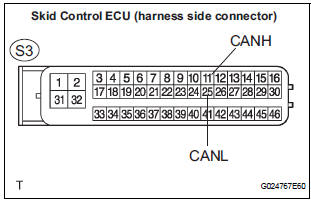
- Turn the ignition switch off.
- Disconnect the skid control ECU with Actuator connector.
- Measure the resistance according to the value(s) in the table below.
Standard resistance

2 CHECK WIRE HARNESS (IG1, GND1, GND2)

- Measure the resistance according to the value(s) in the table below.
Standard resistance

- Measure the voltage according to the value(s) in the table below.
Standard voltage

REPLACE ABS & TRACTION ACTUATOR ASSEMBLY
 Fail-safe chart
1. FAIL-SAFE FUNCTION
When communication fails in any of the main wires
(communication lines) due to a short circuit or other
causes, the fail-safe function, which is specified for
each syst ...
 Distance Control ECU Communication Stop Mode
DESCRIPTION
Detection Item
Symptom
Trouble Area
Distance Control ECU
Communication Stop
Mode
Distance control" is not displayed on the
&qu ...
Other materials:
Camshaft Position "A" Actuator Circuit
DESCRIPTION
The Variable Valve Timing (VVT) system includes the ECM, Oil Control Valve
(OCV) and VVT controller.
The ECM sends a target duty-cycle control signal to the OCV. This control signal
regulates the oil
pressure supplied to the VVT controller. Camshaft timing control is perform ...
Disposal
HINT:
Use the same procedures for the RH side and LH side.
The procedures listed below are for the LH side.
When scrapping a vehicle equipped with the SRS or
disposing of the curtain shield airbag assembly, be sure to
deploy the airbag first in accordance with the proce ...
Terminals of ECU
1. CLEARANCE WARNING ECU
*1: with Front Clearance Sonar
2. AIR CONDITIONER AMPLIFIER ASSEMBLY
*1: with Front Clearance Sonar
*2: Manual A/C
*3: Auto A/C
Reference: waveform 1
HINT:
Terminal: CBZ - E, BBZ - E, Z- - Body ground
Gauge set: 2 ...