Toyota Sienna Service Manual: Stuck in Deceleration Sensor
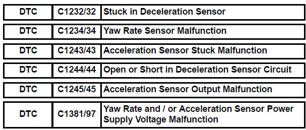
DESCRIPTION
The yaw rate sensor and deceleration sensor signal is sent to the skid control ECU through the CAN communication system. When there is a malfunction in the communication, it will be detected by the diagnosis function.

WIRING DIAGRAM

INSPECTION PROCEDURE
HINT: When U0073/94, U0100/65, U0123/62, U0124/95 or U0126/63 are output accompanied with C1232/32, C1234/34, C1243/43, C1244/44, C1245/45 or C1381/97, inspect and repair the trouble areas indicated by U0073/94, U0100/65, U0123/62, U0124/95 or U0126/63 first.
1 CHECK YAW RATE AND DECELERATION SENSOR INSTALLATION
(a) Check that the yaw rate and deceleration sensor has been installed properly (See page BC-197).
OK: The sensor should be tightened to the specified torque.
The sensor should not be tilted.


2 INSPECT YAW RATE AND DECELERATION SENSOR (IG TERMINAL)
(a) Disconnect the yaw rate and deceleration sensor connector.

(b) Turn the ignition switch to the ON position.
(c) Measure the voltage according to the value(s) in the table below.
Standard voltage 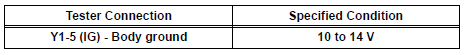

3 INSPECT YAW RATE AND DECELERATION SENSOR (GND TERMINAL)

(a) Disconnect the yaw rate and deceleration sensor connector.
(b) Measure the resistance according to the value(s) in the table below.
Standard resistance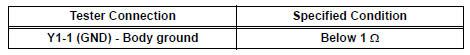

REPLACE YAW RATE AND DECELERATION SENSOR
 Steering Angle Sensor Circuit Malfunction
DTC C1231/31 Steering Angle Sensor Circuit Malfunction
DESCRIPTION
The steering angle sensor signal is sent to the skid control ECU through the
CAN communication system.
When there is a malfunc ...
 Low Battery Positive Voltage
DTC C1241/41 Low Battery Positive Voltage
DESCRIPTION
WIRING DIAGRAM
INSPECTION PROCEDURE
1 INSPECT ECU-IG FUSE
(a) Remove the ECU-IG fuse from the driver side J/B.
(b) Check continu ...
Other materials:
Mirror Switch Circuit
DESCRIPTION
A switch signal of the outer mirror switch is transmitted to the
selected outer mirror control ECU by way
of the body ECU. Then, the outer mirror control ECU activates the mirror
motor to move the mirror UP,
DOWN, RIGHT and LEFT in response to the inputs.
HINT:
Th ...
Short to GND in Curtain Shield Squib RH Circuit
DTC B1162/81 Short to GND in Curtain Shield Squib RH Circuit
DESCRIPTION
The curtain shield squib RH circuit consists of the center airbag sensor
assembly and the curtain shield
airbag assembly RH.
The circuit instructs the SRS to deploy when deployment conditions are met.
DTC B1162/81 is ...
Disassembly
1. Remove park/neutral position switch assembly
(A) remove the nut, washer and control shaft lever.
(B) using a screwdriver, unstake the nut stopper, and
remove the lock nut and nut stopper.
(c) Remove the 2 bolts and pull out the park/neutral
position switch.
2. REMOVE BREATHER PLUG H ...