Toyota Sienna Service Manual: System diagram
1. DISC PLAYER OUTLINE
- A CD player uses a laser pickup to read digital signals recorded on CDs. By converting the digital signals to analog, music and other content can be played.
CAUTION: Do not look directly at the laser pickup because the CD player uses an invisible laser beam. Be sure to operate the player only as instructed.
NOTICE:
- Do not disassemble any part of the CD player.
- Do not apply oil to the CD player.
- Do not insert anything but a CD into the CD player.
- Usable discs
- The CD player can only play audio CDs, CD-Rs (CD-Recordable), and CD-RWs (CDReWritable) that have any of the following marks:

- Precautions for use of discs
NOTICE:
- Copy-protected CDs cannot be played.
- CD-Rs and CD-RWs may not be played depending on the recording conditions or characteristics of the discs, or due to damage, dirt, or deterioration caused by leaving the discs in the cabin for a long time.
- Unfinalized CD-Rs and CD-RWs cannot be played.
- Keep the discs away from dirt. Be careful not to damage the discs or leave your fingerprints on them.
- Hold discs by the outer edge and center hole with the label side up.
- Leaving the disc exposed halfway out of the slot for a long time after pressing the disc eject button may cause deformation of the disc, making the disc unusable.
- If discs have adhesive tape, stickers, CDR labels, or any traces of such labels attached, the discs may not be ejected or player malfunctions may result.
- Keep the discs away from direct sunlight.
(Exposure to direct sunlight may cause deformation of the disc, making the disc unusable.)
- Do not use odd-shaped CDs because these may cause player malfunctions.
- Do not use discs whose recording portion is transparent or translucent because they may not be inserted, ejected, or played normally.
HINT:
- When it is cold or it is raining, if the windows mist up, mist and also dew may form in the player. In such a case, the CD may skip or the CD may stop in the middle of play. Ventilate or dehumidify the cabin for a while before using the player.
- The CD may skip if the player experiences strong vibrations when the vehicle is driven on rough road or similar uneven surface(s).
- Cleaning
NOTICE: Do not use a lens cleaner because it may cause a malfunction in the pickup portion of the player.
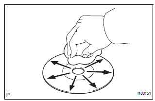
- If dirt is on the disc surface, wipe it clean with a soft dry cloth such as an eyeglass cleaner for plastic lenses from the inside to the outside in a radial direction.
NOTICE:
- Pressing on the disc by hand or rubbing the disc with a hard cloth may scratch the disc surface.
- Use of solvent such as a record spray, antistatic agent, alcohol, benzine, and thinner, or a chemical cloth may cause damage to the disc, making the disc unusable.
2. MP3/WMA OUTLINE
- Playable MP3 file standards
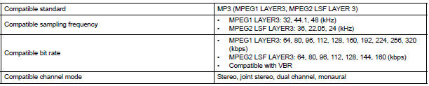
- Playable WMA file standards

- ID3 tag and WMA tag
- Additional textual information called ID3 tag can
be input to MP3 files. Information such as song
titles and artist names can be stored.
HINT: This player is compatible with the ID3 tags of ID3 Ver. 1.0 and 1.1, and ID3 Ver. 2.2 and 2.3.
(Number of characters complies with ID3 Ver.
1.0 and 1.1.)
- Additional textual information called WMA tag can be input to WMA files. Information such as song titles and artist names can be stored.
- Usable media
- Only CD-ROMs, CD-Rs (CD-Recordable), and CD-RWs (CD-ReWritable) only can be used to play MP3/WMA files.
NOTICE:
- CD-Rs and CD-RWs are more easily affected by a hot and humid environment than discs used for normal audio CDs. For this reason, some CD-Rs and CD-RWs may not be played.
- If there are fingerprints or scratches on the disc, the disc may not be played or the CD may skip.
- Some CD-Rs and CD-RWs deteriorate if they are left in the cabin for a long time.
- Keep CD-Rs and CD-RWs in a storage case that is impenetrable to light.
- Usable media format
- Usable media format

HINT:
- As for MP3/WMA files written in any format other than those above, the contents of the files may not be played normally or the file names or folder names may not be displayed correctly.
- This player is compatible with multi-session discs and can play CD-Rs and CD-RWs on which MP3/WMA files are added. However, only the first session can be played.
- Discs whose first session includes both music data and MP3 or WMA format data cannot be played.
- Standard and restrictions

- File names
- Only files with an extension of ".mp3" or ".wma" can be recognized and played as MP3 or WMA files.
- Save MP3 or WMA files with an extension of ".mp3" or ".wma".
NOTICE: If saving non-MP3 or non-WMA files with an extension of ".mp3" or ".wma", those files are wrongly recognized as MP3 or WMA files and played. A loud noise may occur and damage to the speaker may result.
3. AVC-LAN DESCRIPTION
- What is AVC-LAN?

AVC-LAN, an abbreviation for "Audio Visual Communication Local Area Network", is a united standard developed by the manufacturers in affiliation with Toyota Motor Corporation. This standard pertains to audio and visual signals as well as switch and communication signals.
- Purpose:
Recently, car audio systems have rapidly developed and the functions have vastly changed. The conventional car audio system is being integrated with multi-media interfaces similar to those in navigation systems. At the same time, customers are demanding higher quality from their audio systems. This is merely an overview of the standardization background. The specific purposes are as follows:
- To solve sound problems, etc. caused by using components of different manufacturers through signal standardization.
- To allow each manufacturer to concentrate on developing products they do best. From this, reasonably priced products can be produced.
HINT:
- If a short to +B or short to ground is detected in the AVC-LAN circuit, communication is interrupted and the audio system will stop functioning.
- If an audio system is equipped with a navigation system, the multi-display unit acts as the master unit. If the navigation system is not equipped, the audio head unit acts as the master unit instead. If the radio and navigation assembly is equipped, it is the master unit.
- The radio receiver contains a resistor that is necessary to enable communication on the different AVC-LAN circuits.
- The car audio system with an AVC-LAN circuit has a diagnostic function.
- Each component has a specified number (3- digit) called a physical address. Each function has a number (2-digit) called a logical address.
4. COMMUNICATION SYSTEM OUTLINE
- Components of the audio system communicate with each other via the AVC-LAN.
- The master component of the AVC-LAN is a radio receiver with a 60 to 80 Ω resistor. This is essential for communication.
- If a short circuit or open circuit occurs in the AVCLAN circuit, communication is interrupted and the audio system will stop functioning.
5. DIAGNOSTIC FUNCTION OUTLINE
- The audio system has a diagnostic function (the result is indicated on the master unit).
- A 3-digit hexadecimal component code (physical address) is allocated to each component on the AVC-LAN. Using this code, the component in the diagnostic function can be displayed.
 Audio and visual system
PARTS LOCATION
SYSTEM DIAGRAM
...
 How to proceed with
troubleshooting
How to proceed with
troubleshooting
1 VEHICLE BROUGHT TO WORKSHOP
2 INSPECT BATTERY VOLTAGE
Standard voltage:
11 to 14 V
If the voltage is below 11 V, recharge or replace the battery
before proceeding.
3 BASIC INSPECTION
Turn ...
Other materials:
Removal
1. REMOVE BACK DOOR CENTER GARNISH (See page
ET-18)
2. REMOVE POWER BACK DOOR ROD (See page ED-
220)
3. REMOVE BACK DOOR LH SIDE GARNISH
4. REMOVE BACK DOOR RH SIDE GARNISH
5. REMOVE BACK DOOR PULL STRAP (See page ED-
221)
6. REMOVE BACK DOOR TRIM BOARD ASSEMBLY
7. REMOVE LH BACK-UP LIGH ...
Initialization
1. RESET
Reset the power slide door system:
The power slide door ECU records the fully open
position of the power slide door in its memory and
the power slide door fully opens and closes based
on this memory. The power slide door cannot
operate without this memory. In the case wh ...
How to proceed with
troubleshooting
HINT:
Use this procedure to troubleshoot the front power seat
control system.
The intelligent tester should be used in steps 3 and 5.
1 VEHICLE BROUGHT TO WORKSHOP
2 CUSTOMER PROBLEM ANALYSIS CHECK AND PROBLEM SYMPTOM CHECK
3 CHECK COMMUNICATION FUNCTION OF MULTIPLEX COMMUNI ...