Toyota Sienna Service Manual: TC and CG Terminal Circuit
DESCRIPTION
Connecting terminals TC and CG of the DLC3 causes the system to enter the self-diagnostic mode. If a malfunction is present, DTCs will be output.
HINT: When a particular warning light remains blinking, a ground short in the wiring of terminal TC of the DLC3 or an internal ground short in the relevant ECU is suspected.
WIRING DIAGRAM
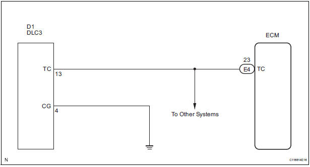
INSPECTION PROCEDURE
1 CHECK HARNESS AND CONNECTOR (TERMINAL TC of DLC3 - ECM)

- Disconnect the E4 connector from the ECM.
- Measure the resistance according to the value(s) in the table below.
Standard resistance

2 CHECK HARNESS AND CONNECTOR (TERMINAL CG of DLC3 - BODY GROUND)

- Measure the resistance according to the value(s) in the table below.
Standard resistance

3 CHECK HARNESS AND CONNECTOR (TERMINAL TC of DLC3 - BODY GROUND)

- Measure the resistance according to the value(s) in the table below.
Standard resistance

PROCEED TO NEXT CIRCUIT INSPECTION SHOWN IN PROBLEM SYMPTOMS TABLE
 Cruise Main Indicator Light Circuit
DESCRIPTION
When the cruise control main switch is on, the CRUISE main indicator light
and READY indicator light
come on. This indicates the control condition (presence or absence of a vehicle
i ...
 Cruise control main switch
COMPONENTS
Removal
1. DISCONNECT BATTERY NEGATIVE TERMINAL
2. REMOVE STEERING WHEEL COVER LOWER NO.2
(24)
3. REMOVE STEERING WHEEL COVER LOWER NO.3
(24)
4. REMOVE HORN BUTTON ASSEMBLY
...
Other materials:
Starter Relay Circuit High
MONITOR DESCRIPTION
While the engine is being cranked, the positive battery voltage is applied to
terminal STA of the ECM.
If the ECM detects the Starter Control (STA) signal while the vehicle is being
driven, it determines that
there is a malfunction in the STA circuit. The ECM then il ...
Installation
1. INSTALL VVT SENSOR (for Bank 2 Exhaust Side)
Install the VVT sensor with the bolt.
Torque: 10 N*m (102 kgf*cm, 7 ft.*lbf)
Connect the VVT sensor connector.
2. INSTALL VVT SENSOR (for Bank 2 Intake Side)
Install the VVT sensor with the bolt.
Torque: 10 N* ...
Parking Brake Switch Circuit
DESCRIPTION
The Multiplex network body ECU receives parking brake switch signal.
WIRING DIAGRAM
INSPECTION PROCEDURE
1 READ VALUE OF INTELLIGENT TESTER
Connect the intelligent tester to DLC3.
Turn the ignition switch ON and push the intelligent
tester main switch ON.
Se ...