Toyota Sienna Service Manual: Terminals of ECM
1. SFI SYSTEM

HINT: The standard normal voltage between each pair of the ECM terminals is shown in the table below. The appropriate conditions for checking each pair of the terminals are also indicated.
The check results should be compared with the standard normal voltage for that pair of terminals, listed in the "Specified Condition" column.
The illustration above can be used as a reference to identify the ECM terminal locations.


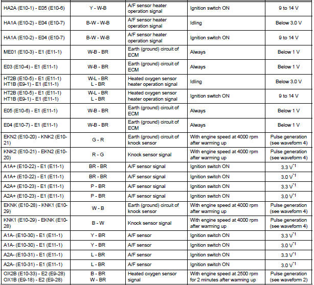
*1: The ECM terminal voltage is constant regardless of the output voltage from the sensor.

- WAVEFORM 1
- Camshaft Timing Oil Control Valve (OCV) operation signal

HINT: The wavelength becomes shorter as the engine rpm increases.

- WAVEFORM 2
- Heated oxygen sensor signal

HINT: In the DATA LIST, item O2S B1S2 shows the ECM input values from the heated oxygen sensor.

- WAVEFORM 3
- Fuel injector operation signal

HINT: The wavelength becomes shorter as the engine rpm increases.

- WAVEFORM 4
- Knock sensor signal

HINT:
- The wavelength becomes shorter as the engine rpm increases.
- The waveforms and amplitudes displayed differ slightly depending on the vehicle.

- WAVEFORM 5
- Variable Valve Timing (VVT) sensor signal (1)
- Crankshaft position sensor signal (2)

HINT: The wavelength becomes shorter as the engine rpm increases.

- WAVEFORM 6
- Igniter IGT signal (from ECM to igniter) (1)
- Igniter IGF signal (from igniter to ECM) (2)

HINT: The wavelength becomes shorter as the engine rpm increases.

- WAVEFORM 7
- Purge VSV for EVAP system operation signal

HINT: If the waveform is not similar to that shown in the illustration, check the waveform again after idling for 10 minutes or more.

- WAVEFORM 8
- Vehicle speed signal

HINT:
- The wavelength becomes shorter as the vehicle speed increases.
- Depending on the vehicle, the output waveform voltage may rise to 12 V if influenced by optionally installed systems.

- WAVEFORM 9
- Throttle drive motor operation signal (positive terminal)

HINT: The duty ratio varies depending on the throttle actuator operation.

- WAVEFORM 10
- Throttle drive motor operation signal (negative terminal)

HINT: The duty ratio varies depending on the throttle actuator operation.

- WAVEFORM 11
- Engine speed signal

HINT: The wavelength becomes shorter as the engine rpm increases.
 Problem symptoms table
HINT:
When a malfunction is not confirmed by a DTC (Diagnostic
Trouble Code) check and the cause of problem cannot be
identified through a basic inspection, troubleshoot according
to the priority ...
 Diagnosis system
1. DESCRIPTION
When troubleshooting OBD II (On-Board
Diagnostics) vehicles, an intelligent tester
(complying with SAE J1987) must be connected to
the DLC3 (Data Link Connector 3) o ...
Other materials:
Inspection
1. INSPECT UNDERDRIVE PACK CLEARANCE
(a) Install the underdrive clutch to the transaxle case.
NOTICE:
Be careful not to damage the oil seal rings.
(b) Install a dial indicator as shown in the illustration.
(c) Measure the underdrive clutch pack clearance while
applying and releasing comp ...
Pressure Control Solenoid "C" Performance (Shift
Solenoid Valve SL3)
SYSTEM DESCRIPTION
The ECM uses signals from the vehicle speed sensor to detect the actual gear
position (1st, 2nd, 3rd, 4th
or 5th gear).
Then the ECM compares the actual gear with the shift schedule in the ECM memory
to detect mechanical
troubles of the shift solenoid valves and valve bo ...
Reassembly
1. INSTALL REAR DISC
(a) Aligning the matchmarks, install the rear disc.
HINT:
Select the installation position where the disc has
the minimum runout.
2. INSPECT DISC RUNOUT
(a) Temporarily fasten the disc with the hub nuts.
Torque: 103 N*m (1,050 kgf*cm, 76 ft.*lbf)
(b) Using a di ...