Toyota Sienna Service Manual: Terminals of ECU
1. CHECK TRANSPONDER KEY AMPLIFIER
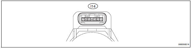
- Disconnect the I14 amplifier connector and measure the resistance between the terminal of the wire harness side connector and body ground.

If the result is not as specified, there may be a malfunction on the wire harness side.
- Reconnect the I14 amplifier connector and measure the resistance and voltage of each terminal of the connector

If the result is not as specified, the amplifier may have a malfunction.

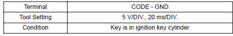
- Inspect using an oscilloscope.
- Waveform 1 (Reference):
- Waveform 2 (Reference):

2. CHECK TRANSPONDER KEY ECU ASSEMBLY
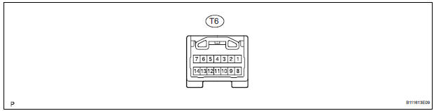
- Disconnect the T6 ECU connector and measure the resistance and voltage between each terminal of the wire harness side connector

If the result is not as specified, there may be a malfunction on the wire harness side.
- Reconnect the T9 ECU connector and measure the voltage of each terminal of the connector.

If the result is not as specified, the ECU may have a malfunction.

- Inspect using an oscilloscope.
- Wave form 1 (Reference):

- Wave form 2 (Reference):

- Wave form 3 (Reference):

- Wave form 4 (Reference):
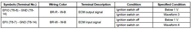
3. CHECK ECM

- Disconnect the E11 ECM connector and measure the resistance between the terminal of the wire harness side connector and body ground.

If the result is not as specified, there may be a malfunction on the wire harness side.
- Reconnect the E11 ECM. Measure the voltage between each terminal of the connector according to the value(s) in the table below.

If the result is not as specified, there may be a malfunction on the wire harness side.

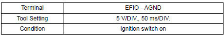
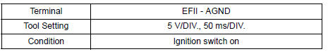
- Inspect using an oscilloscope.
- Waveform 1 (Reference):
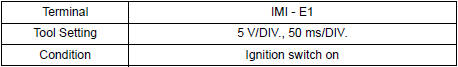
- Waveform 2 (Reference):

 Problem symptoms table
ENGINE IMMOBILISER SYSTEM
...
 Diagnosis system
1. CHECK DLC3
The vehicle's ECU uses ISO 15765-4 for
communication protocol. The terminal arrangement
of the DLC3 complies with SAE J1962 and matches
the ISO 15765-4 format.
...
Other materials:
Slide Door Closer LH does not Operate
DESCRIPTION
The slide door ECU LH controls the slide door closer. In response to the
output signals from the switches
in the slide door lock, the slide door closer drives the closer motor.
HINT:
The slide door closer system operates regardless of the power slide door main
switch ON / OFF.
W ...
Engine hood courtesy
switch
Inspection
1. INSPECT ENGINE HOOD COURTESY SWITCH
Measure the resistance according to the value(s) in
the table below.
Standard resistance
If the result is not as specified, replace the hood lock
assembly. ...
Removal
1. DISCHARGE FUEL SYSTEM PRESSURE
HINT:
See page FU-1.
2. DISCONNECT CABLE FROM NEGATIVE BATTERY
TERMINAL
3. REMOVE NO. 1 ENGINE UNDER COVER
4. DRAIN ENGINE COOLANT (See page CO-6)
5. REMOVE FRONT WIPER ARM HEAD CAP (See page
WW-4)
6. REMOVE FRONT WIPER ARM RH (See page WW-4)
7. REMOVE FRO ...