Toyota Sienna Service Manual: Throttle Actuator Control Motor Current Range / Performance

DESCRIPTION
The ETCS (Electronic Throttle Control System) has a dedicated power supply circuit. The voltage (+BM) is monitored and when it is low (less than 4 V), the ECM determines that there is a malfunction in the ETCS and cuts off the current to the throttle actuator.
When the voltage becomes unstable, the ETCS itself becomes unstable. For this reason, when the voltage is low, the current to the throttle actuator is cut. If repairs are made and the system returns to normal, turn the ignition switch off. The ECM then allows the current to flow to the throttle actuator so that it can be restarted.
HINT:
The ETCS does not use a throttle cable.


MONITOR DESCRIPTION
The ECM monitors the battery supply voltage applied to the throttle actuator.
When the power supply voltage (+BM) drops below 4 V for 0.8 seconds or more, the ECM interprets this as an open in the power supply circuit (+BM). The ECM illuminates the MIL and sets the DTC.
If the malfunction is not repaired successfully, the DTC is set 5 seconds after the engine is next started.
MONITOR STRATEGY


TYPICAL ENABLING CONDITIONS

TYPICAL MALFUNCTION THRESHOLDS

COMPONENT OPERATING RANGE

FAIL-SAFE
When this DTC, as well as other DTCs relating to ETCS (Electronic Throttle Control System) malfunctions, is set, the ECM enters fail-safe mode. During fail-safe mode, the ECM cuts the current to the throttle actuator off, and the throttle valve is returned to a 6° throttle angle by the return spring. The ECM then adjusts the engine output by controlling the fuel injection (intermittent fuel-cut) and ignition timing, in accordance with the accelerator pedal opening angle, to allow the vehicle to continue at a minimal speed. If the accelerator pedal is depressed gently, the vehicle can be driven slowly.
Fail-safe mode continues until a pass condition is detected, and the ignition switch is then turned off.
WIRING DIAGRAM

INSPECTION PROCEDURE
HINT:
Read freeze frame data using the intelligent tester. The ECM records vehicle and driving condition information as freeze frame data the moment a DTC is stored. When troubleshooting, freeze frame data can be helpful in determining whether the vehicle was running or stopped, whether the engine was warmed up or not, whether the air-fuel ratio was lean or rich, as well as other data recorded at the time of a malfunction.
1 CHECK FUSE (ETCS FUSE)

(a) Remove the ETCS fuse from the engine room junction block.
(b) Measure the resistance according to the value(s) in the table below.
Standard resistance: Below 1 Ω
(c) Reinstall the ETCS fuse.


2 INSPECT ECM (+BM VOLTAGE)

(a) Measure the voltage according to the value(s) in the table below.
Standard voltage 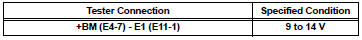


3 CHECK HARNESS AND CONNECTOR (ECM - ETCS FUSE)

(a) Check the harness and connector between the ETCS fuse and ECM.
(1) Remove the ETCS fuse from the engine room junction block.
(2) Disconnect the E4 ECM connector.
(3) Measure the resistance according to the value(s) in the table below.
Standard resistance: 
(4) Reconnect the ECM connector.


4 CHECK HARNESS AND CONNECTOR (ETCS FUSE - BATTERY)

(a) Check the harness and connector between the ETCS fuse and positive battery cable.
(1) Disconnect the negative battery cable.
(2) Measure the resistance according to the value(s) in the table below.
Standard resistance: 
(3) Reinstall the ETCS fuse.
(4) Reconnect the negative battery cable.


REPLACE ECM (See page ES-498)
 Throttle Actuator Control System
DESCRIPTION
The throttle actuator is operated by the ECM, and opens and closes the
throttle valve using the gears.
The opening angle of the throttle valve is detected by the Throttle Positio ...
 Throttle Actuator Control Throttle Body Range / Performance
DESCRIPTION
The Electronic Throttle Control System (ETCS) is composed of the throttle
actuator, Throttle Position (TP)
sensor, Accelerator Pedal Position (APP) sensor, and ECM. The ECM operate ...
Other materials:
Master Cylinder Pressure Sensor Malfunction
DTC C1246/46 Master Cylinder Pressure Sensor Malfunction
DESCRIPTION
Master cylinder pressure sensor is connected to the skid control ECU in the
actuator.
INSPECTION PROCEDURE
1 READ VALUE ON INTELLIGENT TESTER (MASTER CYLINDER PRESSURE SENSOR)
(a) Connect the intelligent tester to the DL ...
Passenger Side Outer Mirror ECU
DTC B1208 Passenger Side Outer Mirror ECU
DESCRIPTION
This DTC is detected when communication between the outer mirror control ECU
RH and multiplex
network gateway ECU stops for more than 10 seconds.
DTC No.
DTC Detecting Condition
Trouble Area
B1208
Pa ...
Inspection
1. INSPECT UNDERDRIVE PLANETARY GEAR PRELOAD
(a) Using SST, fix the underdrive planetary gear
assembly.
SST 09387-00050
(b) Using SST and a torque wrench, measure the
turning torque of the underdrive planetary gear
assembly while rotating the torque wrench at 60
rpm.
SST 09387-00050
...