Toyota Sienna Service Manual: TRAC OFF Indicator Light Remains ON
DESCRIPTION
The skid control ECU is connected to the combination meter via CAN and multiplex communications.
When the traction OFF switch is turned on, the TRAC OFF indicator light will come on (for 2WD model).
WIRING DIAGRAM

INSPECTION PROCEDURE
NOTICE: When replacing the brake actuator assembly, perform zero point calibration (See page BC-70).
1 CHECK CAN COMMUNICATION SYSTEM
(a) Check if the CAN communication system DTC is output (See page CA-17).
Result 


2 CHECK MULTIPLEX COMMUNICATION SYSTEM
(a) Check if the multiplex communication system DTC is output (See page MP-14).
Result 


3 CHECK IF SKID CONTROL ECU CONNECTOR IS SECURELY CONNECTED
(a) Check if the skid control ECU connector is securely connected.
OK: The connector is securely connected.


4 CHECK BATTERY
(a) Check the battery voltage.
Standard voltage: 11 to 14 V


5 INSPECT SKID CONTROL ECU (CSW TERMINAL)

(a) Disconnect the skid control ECU connector.
(b) Measure the resistance according to the value(s) in the table below.
Standard resistance 


6 INSPECT COMBINATION METER ASSEMBLY
(a) Reconnect the skid control ECU connector.
(b) Perform Active Test of the combination meter (meter CPU) using the intelligent tester (See page ME-19).
OK: The TRAC OFF indicator light turns on or off in accordance with the intelligent tester.
HINT: If troubleshooting has been carried out according to the Problem Symptoms Table, refer back to the table and proceed to the next step before replacing the part (See page BC-79).


REPLACE BRAKE ACTUATOR ASSEMBLY
7 INSPECT TRACTION OFF SWITCH
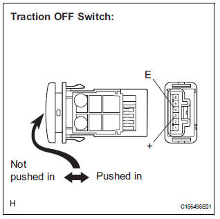
(a) Disconnect the traction OFF switch connector.
(b) Measure the resistance according to the value(s) in the table below.
Standard resistance 


8 CHECK HARNESS AND CONNECTOR (SKID CONTROL ECU - TRACTION OFF SWITCH)

(a) Measure the resistance according to the value(s) in the table below.
Standard resistance 
HINT: If troubleshooting has been carried out according to the Problem Symptoms Table, refer back to the table and proceed to the next step (See page BC-79).


REPLACE BRAKE ACTUATOR ASSEMBLY
 Brake Warning Light Remains ON
DESCRIPTION
The BRAKE warning light comes on when the brake fluid is insufficient, the
parking brake is applied or the
EBD is defective.
WIRING DIAGRAM
INSPECTION PROCEDURE
HINT:
When rele ...
 TRAC OFF Indicator Light does not Come ON
DESCRIPTION
The skid control ECU is connected to the combination meter via CAN and
multiplex communications.
When the traction OFF switch is turned on, the TRAC OFF indicator light will
come o ...
Other materials:
Installation
1. INSTALL SEAT POSITION AIRBAG SENSOR
Check that the ignition switch is off.
Check that the negative battery (-) terminal is
disconnected.
CAUTION:
After disconnecting the negative battery
terminal, wait for at least 90 seconds before
starting the operation.
Usin ...
Short to GND in Front Passenger Side Squib
2nd Step Circuit
DTC B1187/55 Short to GND in Front Passenger Side Squib
2nd Step Circuit
DESCRIPTION
The front passenger side squib 2nd step circuit consists of the center airbag
sensor assembly and the
front passenger airbag assembly.
The circuit instructs the SRS to deploy when deployment conditions are ...
VSC Warning Light does not Come ON
DESCRIPTION
The skid control ECU is connected to the combination meter via CAN and
multiplex communications.
If the skid control ECU stores DTCs to shut down TRAC and VSC operation, the VSC
warning light comes
on in the combination meter.
WIRING DIAGRAM
Refer to VSC Warning Light Remains ...