Toyota Sienna Service Manual: Vehicle Speed Signal Circuit between Stereo Component Amplifier and Combination Meter
DESCRIPTION
This circuit is necessary for the ASL (Auto Sound Leveliser) built into the stereo component amplifier.
Speed signals are received from the combination meter and used for the ASL.
The ASL function automatically adjusts the sound data in order to enable hearing the clear audio sound even when vehicle noise increases (as vehicle noise increases, the volume is turned up etc.).
HINT:
- A voltage of 12 V or 5 V is output from each ECU and then input to the combination meter. The signal is changed to a pulse signal at the transistor in the combination meter. Each ECU controls the respective system based on the pulse signal.
- If a short occurs in an ECU, all systems in the diagram below will not operate normally.
WIRING DIAGRAM

INSPECTION PROCEDURE
1 OPERATION OF SPEEDOMETER
- Drive the vehicle and check if the function of the speedometer on the combination meter is normal.
OK: Actual vehicle speed and the speed indicated on the speedometer are the same.
HINT: The vehicle speed sensor is functioning normally when the indication on the speedometer is normal
2 INSPECT STEREO COMPONENT AMPLIFIER

- Disconnect the stereo component amplifier connector S11.
- Measure the voltage.
- Jack up either one of the drive wheels.
- Move the shift lever to the neutral position.
- Turn the ignition switch to the ON position.
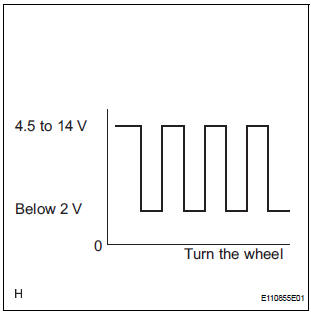
- Measure the voltage between terminal SPD of the stereo component amplifier and body ground when the drive wheels are turned slowly.
OK: Voltage pulses as shown in the illustration.
REPLACE STEREO COMPONENT AMPLIFIER
3 CHECK HARNESS AND CONNECTOR (COMBINATION METER - STEREO COMPONENT AMPLIFIER)

- Disconnect the stereo component amplifier connector S11 and combination meter connector C10.
- Measure the resistance according to the value(s) in the table below.
Standard resistance

4 CHECK HARNESS AND CONNECTOR (COMBINATION METER - STEREO COMPONENT AMPLIFIER)

- Disconnect the stereo component amplifier connector S11 and combination meter connector C10.
- Measure the resistance according to the value(s) in the table below.
Standard resistance

HINT: If the resistance between terminal SPD and body ground is less than 10 kΩ, there may be a short in a wire harness, connector, or an ECU that is connected to the SPD signal wire
REPLACE COMBINATION METER
 Vehicle Speed Signal Circuit between Multi-display and Combination
Meter
Vehicle Speed Signal Circuit between Multi-display and Combination
Meter
DESCRIPTION
This circuit is necessary for the ASL (Auto Sound Leveliser) built into the
radio receiver.
Speed signals are received from the combination meter and used for the ASL.
The ASL fun ...
 Radio Receiver Communication Error
INSPECTION PROCEDURE
1 IDENTIFY THE COMPONENT SHOWN BY THE SUB-CODE
Enter the diagnostic mode
Press the preset switch "3" to change to "Detailed
Information Mode". ...
Other materials:
Power Slide Door LH does not Operate When Using Inside / Outside
Handle
DESCRIPTION
The inside / outside handles have the ability to control operation
of the power slide door. Pulling either
handle transmits a request signal to the power slide door ECU LH, which then
commands the power
slide door control motor and clutch to open / close the power sli ...
Removal
1. REMOVE REAR DOOR SCUFF PLATE
2. REMOVE REAR DOOR WEATHERSTRIP
3. REMOVE BACK DOOR WEATHERSTRIP
4. REMOVE BACK DOOR SCUFF PLATE
5. REMOVE FRONT QUARTER TRIM PANEL ASSEMBLY
Remove the floor anchor cover.
Remove the bolt and disconnect the No. 2 rear seat
outer belt assem ...
High Temperature
DTC 58-45 High Temperature
DTC 80-45 High Temperature
DESCRIPTION
DTC No.
DTC Detection Condition
Trouble Area
58-45
High map disc player temperature is detected (Over
80C).
Radio and navigation assembly
80-45
High map disc player tem ...