Toyota Sienna Service Manual: ACC Power Source Circuit
DESCRIPTION
This circuit supplies power to the A/C amplifier and the illumination for the clock.
WIRING DIAGRAM

INSPECTION PROCEDURE
1 INSPECT FUSE (ECU ACC)
(a) Remove the ECU ACC fuse from the engine room relay block.
(b) Measure the resistance according to the value(s) in the table below.
Standard resistance 


2 CHECK HARNESS AND CONNECTOR (A/C AMPLIFIER - BATTERY)
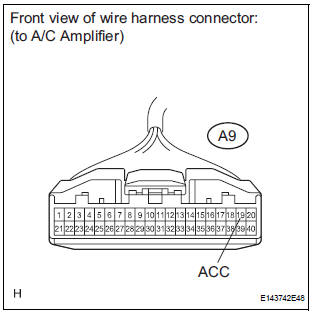
(a) Disconnect the connector from the A/C amplifier.
(b) Measure the voltage according to the value(s) in the table below.
Standard voltage 


PROCEED TO NEXT CIRCUIT INSPECTION SHOWN IN PROBLEM SYMPTOMS TABLE
 IG Power Source Circuit
DESCRIPTION
The main power source is supplied to the A/C amplifier when the ignition
switch is turned to the ON
position.
The power source is used for operating the A/C amplifier and servo moto ...
 Back-up Power Source Circuit
DESCRIPTION
This is the back-up power source for the A/C amplifier. Power is supplied
even when the ignition switch is
off and is used for diagnostic trouble code memory, etc.
WIRING DIAGRAM
...
Other materials:
What to do if... (Troubleshooting)
If there is a problem with the hands-free system or a Bluetooth®
device, first check the table below.
When using the hands-free system with a Bluetooth® device
The hands-free system or Bluetooth® device does not
work.
The connected device may not be a compatible Bl ...
Symptom simulation
HINT:
The most difficult case in troubleshooting is when no
problem symptoms occur. In such a case, a thorough
problem analysis must be carried out. A simulation of the
same or similar conditions and environment in which the
problem occurred in the customer's vehicle should be
carried out. No ...
Installation
HINT:
Install the RH side by the same procedure as the LH side.
1. INSTALL REAR SPEED SENSOR
(a) Clean the contacting surface of the axle hub and a
new skid control sensor.
NOTICE:
Keep the sensor rotor clean.
(b) Place the speed sensor on the axle hub so that the
connector is positioned ...
