Toyota Sienna Service Manual: IG Power Source Circuit
DESCRIPTION
The main power source is supplied to the A/C amplifier when the ignition switch is turned to the ON position.
The power source is used for operating the A/C amplifier and servo motor, etc.
WIRING DIAGRAM

INSPECTION PROCEDURE
HINT: Start the engine before inspection. Check the IG1 relay or battery if the engine does not start.
1 INSPECT FUSE (HTR)
(a) Remove the HTR fuse from the driver side junction block.
(b) Measure the resistance according to the value(s) in the table below.
Standard resistance 


2 INSPECT A/C AMPLIFIER (IG - GND)

(a) Remove the A/C amplifier with its connectors still connected.
(b) Turn the ignition switch to the ON position.
(c) Measure the voltage according to the value(s) in the table below.
Standard voltage 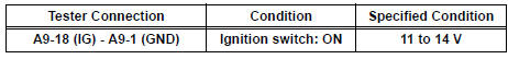


PROCEED TO NEXT CIRCUIT INSPECTION SHOWN IN PROBLEM SYMPTOMS TABLE
3 CHECK HARNESS AND CONNECTOR (A/C AMPLIFIER - BATTERY)

(a) Disconnect the connector from the A/C amplifier.
(b) Measure the voltage according to the value(s) in the table below.
Standard voltage


4 CHECK HARNESS AND CONNECTOR (A/C AMPLIFIER - BODY GROUND)

(a) Measure the resistance according to the value(s) in the table below.
Standard resistance 


REPLACE A/C AMPLIFIER
 Rear Blower Motor Circuit
DESCRIPTION
Power to the rear blower motor is supplied from the battery via the RR A/C
relay.
The rear blower motor speed level varies between 0 and 31 based on the voltage
difference measured ...
 ACC Power Source Circuit
DESCRIPTION
This circuit supplies power to the A/C amplifier and the illumination for the
clock.
WIRING DIAGRAM
INSPECTION PROCEDURE
1 INSPECT FUSE (ECU ACC)
(a) Remove the ECU ACC fuse fr ...
Other materials:
Poor Sound Quality in All Modes (Low Volume)
INSPECTION PROCEDURE
1 CHECK AUDIO SETTINGS
Set "BASS", "MID", and "TREB" to the initial values and
check that sound is normal.
OK:
Malfunction disappears.
2 COMPARE WITH ANOTHER VEHICLE OF SAME MODEL
Compare with another vehicle of the same model.
...
Installation
1. INSTALL SEAT MEMORY SWITCH
2. INSTALL FRONT DOOR TRIM BOARD SUBASSEMBLY
LH
3. INSTALL POWER WINDOW REGULATOR MASTER
SWITCH ASSEMBLY
4. INSTALL FRONT DOOR INSIDE HANDLE BEZEL
PLUG LH
5. INSTALL FRONT DOOR LOWER FRAME BRACKET GARNISH LH
Engage the 4 claws to install the seat me ...
Inspection
1. INSPECT THERMOSTAT
(a) Inspect the thermostat.
HINT:
The valve opening temperature is inscribed on the
thermostat.
(b) Immerse the thermostat in water and gradually heat
the water.
(c) Check the valve opening temperature.
Valve opening temperature:
80 to 84°C (176 to 183°F) ...
