Toyota Sienna Service Manual: Air Conditioning Compressor Magnetic Clutch Circuit
DESCRIPTION
When the A/C amplifier is turned on, a magnetic clutch ON signal is sent from the MGC terminal of the A/ C amplifier. Then, the MG CLT relay turns on to operate the magnetic clutch.
WIRING DIAGRAM

INSPECTION PROCEDURE
1 CHECK CAN COMMUNICATION SYSTEM
(a) Use the intelligent tester to check if the CAN communication system is functioning normally.
Result 


2 CHECK MULTIPLEX COMMUNICATION SYSTEM
(a) Use the intelligent tester to check if the multiplex communication system is functioning normally.
Result 


3 PERFORM ACTIVE TEST BY INTELLIGENT TESTER
(a) Connect the intelligent tester to the DLC3.
(b) Turn the ignition switch to the ON position and turn the intelligent tester main switch on.
(c) Select the item below in the ACTIVE TEST and then check that the relay operates.
ACTIVE TEST / AIR CONDITIONER:
OK: Magnetic clutch relay operates.


PROCEED TO NEXT CIRCUIT INSPECTION SHOWN IN PROBLEM SYMPTOMS TABLE
4 INSPECT FUSE (HTR)
(a) Remove the HTR fuse from the driver side junction block.
(b) Measure the resistance according to the value(s) in the table below.
Standard resistance 
(c) Reconnect the HTR fuse to the driver side junction block.


5 INSPECT RELAY (MG CLT)

(a) Remove the MG CLT relay from the No. 3 relay block.
(b) Measure the resistance according to the value(s) in the table below.
Standard resistance
(c) Install the MG CLT relay to the No. 3 relay block.


6 CHECK HARNESS AND CONNECTOR (A/C AMPLIFIER - BATTERY)

(a) Disconnect the connector from the A/C amplifier.
(b) Measure the voltage according to the value(s) in the table below.
Standard voltage 

7 INSPECT A/C AMPLIFIER

(a) Reconnect the connector to the A/C amplifier.
(b) Measure the voltage according to the value(s) in the table below.
Standard voltage 


8 INSPECT COMPRESSOR AND MAGNETIC CLUTCH

(a) Disconnect the connector from the compressor and magnetic clutch.

(b) Disconnect the connector from the magnetic clutch.
(c) Measure the resistance according to the value(s) in the table below.
Standard resistance 


9 INSPECT MAGNETIC CLUTCH

(a) Measure the resistance according to the value(s) in the table below.
Standard resistance 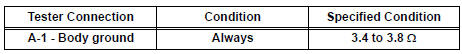
(b) When connector terminal A1 is connected to the positive (+) battery terminal, check that the following occurs: 1) the magnetic clutch's operating sound can be heard, and 2) the magnetic clutch's hub and rotor lock.


10 CHECK HARNESS AND CONNECTOR (NO. 3 RELAY BLOCK - BATTERY)

(a) Remove the MG CLT relay from the No. 3 relay block.
(b) Turn the ignition switch to the ON position.
(c) Measure the voltage according to the value(s) in the table below.
Standard voltage 


REPAIR OR REPLACE HARNESS OR CONNECTOR
 Blower Motor Circuit
DESCRIPTION
The blower motor is operated by signals from the A/C amplifier. Blower motor
speed signals are
transmitted by changes in the Duty Ratio.
Duty Ratio
The duty ratio is the ratio of ...
 Rear Air Conditioning Control Panel Circuit
DESCRIPTION
This is the rear A/C system control signal circuit as well as the power
supply circuit of the rear A/C control
assembly.
Pulse signals regarding rear A/C control panel switch operat ...
Other materials:
System description
1. GENERAL
In conjunction with impact absorbing structure for a
frontal collision, the SRS (Supplemental Restraint
System) driver airbag and front passenger airbag
were designed to supplement seat belts in the event
of a frontal collision in order to help reduce shock to
the head and c ...
Short to GND in Front Passenger Side Squib
2nd Step Circuit
DTC B1187/55 Short to GND in Front Passenger Side Squib
2nd Step Circuit
DESCRIPTION
The front passenger side squib 2nd step circuit consists of the center airbag
sensor assembly and the
front passenger airbag assembly.
The circuit instructs the SRS to deploy when deployment conditions are ...
Control Module Performance
DTC P0607 Control Module Performance
DESCRIPTION
This DTC indicates a malfunction in the ECM.
HINT:
The ECM receives signals from each sensor to control all the functions of the
cruise control with the
microcomputer. When a malfunction is detected, fail-safe remains on until the
ignition sw ...
