Toyota Sienna Service Manual: Air Inlet Damper Position Sensor Circuit
DESCRIPTION

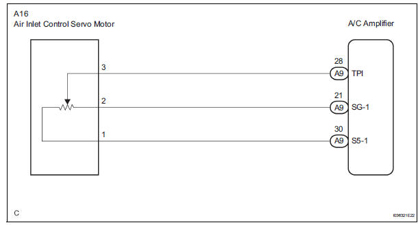
This sensor detects the position of the air inlet control servo motor and sends the appropriate signals to the A/C amplifier. The position sensor is built in the air inlet control servo motor.
The position sensor's resistance changes as the air inlet control servo motor arm moves.
It outputs voltage (5 V) that is input to terminal 1 and terminal 3 via the variable resistor, and then to the A/ C amplifier.
The A/C amplifier determines the arm position based on the input voltage from
the position sensor. 
WIRING DIAGRAM
INSPECTION PROCEDURE
1 READ VALUE OF INTELLIGENT TESTER
(a) Connect the intelligent tester to the DLC3.
(b) Turn the ignition switch to the ON position and turn the intelligent tester main switch on.
(c) Select the items below in the DATA LIST, and read the display on the intelligent tester.
DATA LIST / AIR CONDITIONER 
OK: The display is as specified in the normal condition column.
Result 


2 INSPECT AIR INLET CONTROL SERVO MOTOR

(a) Remove the air inlet control servo motor.
(b) Disconnect the connector from the air inlet control servo motor.
(c) Measure the resistance according to the value(s) in the table below.
Standard resistance 
(d) Measure the resistance according to the value(s) in the table below.
Standard resistance 

(e) As the air inlet control servo motor moves from RECIRCULATION to FRESH, the resistance decreases gradually without interruption.


3 CHECK HARNESS AND CONNECTOR (AIR INLET CONTROL SERVO MOTOR - A/C AMPLIFIER)

(a) Disconnect the connector from the A/C amplifier.

(b) Measure the resistance according to the value(s) in the table below.
Standard resistance


Standard resistance
 Air Mix Damper Position Sensor Circuit (Passenger Side)
DESCRIPTION
This sensor detects the position of the air mix control servo motor (air mix
damper) and sends the
appropriate signals to the A/C amplifier. The position sensor is built in the
a ...
 Air Outlet Damper Position Sensor Circuit
DESCRIPTION
This sensor detects the position of the air outlet control servo motor and
sends the appropriate signals to
the A/C amplifier. The position sensor is built in the air outlet contro ...
Other materials:
Seat Position Airbag Sensor Circuit Malfunction
DTC B1153/25 Seat Position Airbag Sensor Circuit Malfunction
DESCRIPTION
The seat position airbag sensor circuit consists of the center airbag sensor
assembly and the seat
position airbag sensor.
DTC B1153/25 is recorded when a malfunction is detected in the seat position
airbag sensor cir ...
Crankshaft position sensor
Components
Removal
1. Remove compressor and magnetic clutch
HINT:
(See page AC-227 )
2. REMOVE CRANKSHAFT POSITION SENSOR
(a) Disconnect the crankshaft position sensor
connector.
(b) Remove the bolt, and then remove the crankshaft
position sensor.
INSPECTION
1. INSPECT CRANKSHAFT ...
Diagnostic trouble code chart
COMMUNICATION DIAGNOSIS:
DVD PLAYER:
CD PLAYER
IN-DASH CD CHANGER
...
