Toyota Sienna Service Manual: Air Outlet Damper Position Sensor Circuit
DESCRIPTION

This sensor detects the position of the air outlet control servo motor and sends the appropriate signals to the A/C amplifier. The position sensor is built in the air outlet control servo motor. The position sensor's resistance changes as the air outlet control servo motor arm moves.
It outputs voltage (5 V) that is input to terminal 2 and terminal 3 via the
variable resistor, and then to the A/
C amplifier. The A/C amplifier determines the arm position based on the input
voltage from the position
sensor. 
WIRING DIAGRAM

INSPECTION PROCEDURE
1 READ VALUE OF INTELLIGENT TESTER
(a) Connect the intelligent tester to the DLC3.
(b) Turn the ignition switch to the ON position and turn the intelligent tester main switch on.
(c) Select the items below in the DATA LIST, and read the displays on the intelligent tester.
DATA LIST / AIR CONDITIONER 
OK: The display is as specified in the normal condition column.
Result 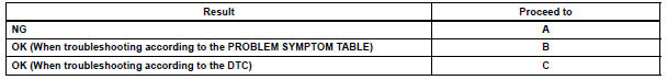


2 INSPECT AIR OUTLET CONTROL SERVO MOTOR
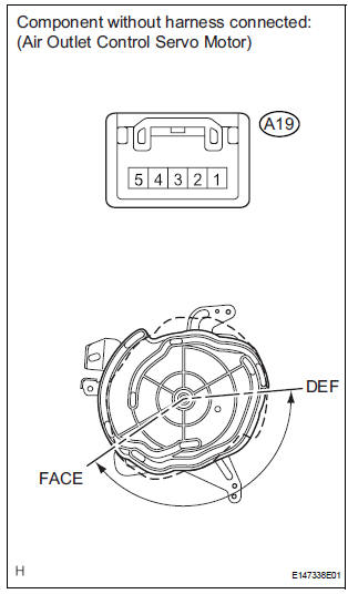
(a) Remove the air outlet control servo motor.
(b) Disconnect the connector from the air outlet control servo motor.
(c) Measure the resistance according to the value(s) in the table below
Standard resistance 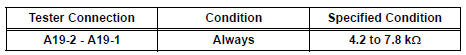
(d) Measure the resistance according to the value(s) in the table below.
Standard resistance 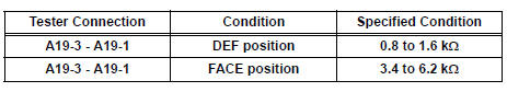
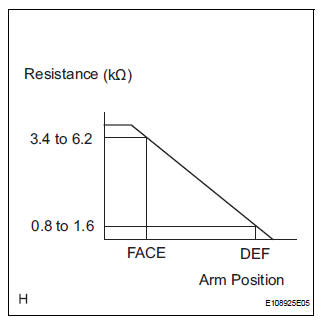
(e) As the air outlet control servo motor moves from the FACE side to the DEF side, the resistance decreases gradually without interruption.

3 CHECK HARNESS AND CONNECTOR (AIR OUTLET CONTROL SERVO MOTOR - A/C AMPLIFIER)

(a) Disconnect the connector from the A/C amplifier.
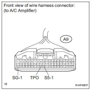
(b) Measure the resistance according to the value(s) in the table below.
Standard resistance 


REPLACE A/C AMPLIFIER
 Air Inlet Damper Position Sensor Circuit
DESCRIPTION
This sensor detects the position of the air inlet control servo motor and
sends the appropriate signals to
the A/C amplifier. The position sensor is built in the air inlet control ...
 Air Mix Damper Position Sensor Circuit (Driver Side)
DESCRIPTION
This sensor detects the position of the air mix control servo motor (air
outlet damper) and sends the
appropriate signals to the A/C amplifier. The position sensor is built in the ...
Other materials:
Front Airbag Sensor RH Circuit Malfunction
DTC B1148/36 Front Airbag Sensor RH Circuit Malfunction
DESCRIPTION
The front airbag sensor RH circuit consists of the center airbag sensor
assembly and front airbag sensor
RH. If the center airbag sensor assembly receives signals from the front airbag
sensor RH, it judges
whether or not the ...
Tire size
Typical tire size information
The illustration indicates typical tire size.
Tire use
(P = Passenger car,
T = Temporary use)
Section width (millimeters)
Aspect ratio
(tire height to section width)
Tire construction code
(R = Radial, D = Diagonal)
Wheel diameter (inches)
...
Precaution
1. INSPECTION PROCEDURE FOR VEHICLE INVOLVED
IN ACCIDENT
Perform the zero point calibration and sensitivity
check if any of the following conditions occur.
The occupant classification ECU is replaced.
Accessories (seatback tray and seat cover, etc.)
are installed.
...
