Toyota Sienna Service Manual: CAN Bus Line
DESCRIPTION
When any DTC for the CAN communication system is output, first measure the resistance between the terminals of the DLC3 to specify the trouble area, and check that there is no short in the CAN main wire, between the main wire, and +B or GND.
WIRING DIAGRAM


INSPECTION PROCEDURE
NOTICE:
- Turn the ignition switch off before measuring the resistances of CAN bus main wires and CAN bus branch wires.
- After the ignition switch is turned off, check that the key reminder warning system and light reminder warning system are not in operation.
- Before measuring the resistance, leave the vehicle as is for at least 1 minute and do not operate the ignition switch, any other switches, or the doors. If any doors need to be opened in order to check connectors, open the doors and leave them open.
HINT: Operating the ignition switch, any switches, or any doors triggers related ECU and sensor communication with the CAN. This communication will cause the resistance value to change.
1 CHECK CAN BUS WIRE (MAIN WIRE FOR DISCONNECTION, CAN BUS LINES FOR SHORT CIRCUIT)

- Turn the ignition switch off.
- Measure the resistance according to the value(s) in the table below.
Standard resistance

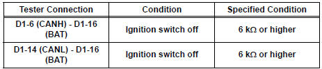
2 CHECK FOR SHORT TO B+ IN CAN BUS WIRE

- Measure the resistance according to the value(s) in the table below.
Standard resistance
3 CHECK FOR SHORT TO GND IN CAN BUS WIRE

- Measure the resistance according to the value(s) in the table below.
Standard resistance

GO TO HOW TO PROCEED WITH TROUBLESHOOTING
 ECM Communication Stop Mode
DESCRIPTION
Detection Item
Symptom
Trouble Area
ECM Communication Stop
Mode
"Engine" is not displayed on the "Communication
Bus Che ...
 Open in CAN Main Bus Line
DESCRIPTION
There may be an open circuit in the CAN main bus wire and/or the DLC3 branch
wire when the resistance
between terminals 6 (CANH) and 14 (CANL) of the DLC3 is 69 Ω or higher.
...
Other materials:
Brake Switch
DESCRIPTION
The stop light switch is a duplex system that transmits two signals: STP and
ST1-. These two signals are
used by the ECM to monitor whether or not the brake system is working properly.
If the signals, which
indicate the brake pedal is being depressed or released, are detected ...
Diagnostic trouble code chart
If a malfunction code is displayed during the DTC check,
check the circuit listed for that code in the table below.
(Proceed to the page given for that circuit.)
POWER BACK DOOR SYSTEM
DTC No.
Detection Item
Trouble Area
B2222
PBD Pulse Sensor Malfuncti ...
Inspection
1. INSPECT RUNOUT OF DIFFERENTIAL RING GEAR
(a) Using a dial gauge , check the runout of the ring
gear.
Maximum runout:
0.07 mm (0.0028 in.)
If the runout is greater than the maximum, replace
the ring gear with a new one.
2. INSPECT DIFFERENTIAL RING GEAR BACKLASH
(a) Using a dial gauge, ...
