Toyota Sienna Service Manual: Disassembly
1. REMOVE BLOWER ASSEMBLY

(a) Remove the 2 screws and the blower assembly.
2. REMOVE MODE DAMPER SERVO SUB-ASSEMBLY

(a) Remove the 3 screws and the mode damper servo sub-assembly.
3. REMOVE AIRMIX DAMPER SERVO SUB-ASSEMBLY

(a) Remove the 3 screws and the airmix damper servo sub-assembly.
4. REMOVE NO. 2 AIRMIX DAMPER SERVO SUBASSEMBLY (for Automatic Air Conditioning System)
(a) Remove the 3 screws and the No. 2 airmix damper servo sub-assembly.
5. REMOVE NO. 1 HEATER CLAMP
(a) Release the 4 claw fittings and remove the No. 1 heater clamp.
6. REMOVE NO. 3 AIR CONDITIONING RADIATOR BRACKET

(a) Remove the screw and the No. 3 air conditioning radiator bracket.
7. REMOVE HEATER RADIATOR UNIT SUB-ASSEMBLY

(a) Remove the heater radiator unit sub-assembly from the air conditioning radiator assembly.
8. REMOVE AIR CONDITIONING TUBE ASSEMBLY

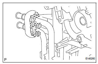
(a) Using a hexagon wrench 4.0 mm (0.15 in.), remove the 2 hexagon bolts and the air conditioning tube assembly.
(b) Remove the 2 O-rings from the air conditioning tube assembly.
9. REMOVE COOLER EXPANSION VALVE

(a) Remove the cooler expansion valve from the No. 1 cooler evaporator sub-assembly.

(b) Remove the 2 O-rings from the No. 1 cooler evaporator sub-assembly.
10. REMOVE NO. 2 AIR CONDITIONING RADIATOR BRACKET

(a) Remove the 2 screws and the No. 2 air conditioning radiator bracket.
11. REMOVE NO. 1 AIR CONDITIONING RADIATOR BRACKET

(a) Remove the 3 screws and the No .1 air conditioning radiator bracket.
12. REMOVE NO. 4 AIR CONDITIONING RADIATOR BRACKET

(a) Remove the No. 4 air conditioning radiator bracket.
13. REMOVE NO. 1 AIR DUCT

(a) Release the 4 claw fittings and remove the No. 1 air duct.
14. REMOVE NO. 1 COOLER THERMISTOR

(a) Disengage the clamp.
(b) Remove the 2 screws.

(c) Remove the 11 screws.

(d) Remove the No. 1 cooler thermistor.
 Removal
1. RECOVER REFRIGERANT FROM REFRIGERATION
SYSTEM (See page AC-172)
2. REMOVE FRONT WIPER ARM HEAD CAP (See page
WW-4)
3. REMOVE FRONT WIPER ARM RH (See page WW-4)
4. REMOVE FRONT WIPER ARM LH (Se ...
 Reassembly
1. INSTALL NO. 1 COOLER THERMISTOR
(a) Install the No. 1 cooler thermistor as shown in the
illustration.
NOTICE:
Be sure to insert the thermistor only once
because reinserting it will no ...
Other materials:
Registering a new contact to the contact list
New contact data can be registered. Up to 4 numbers per person can be
registered. For PBAP compatible Bluetooth® phones, this function is available
when “Automatic Transfer” is set to off.
Select “New Contact”.
Enter the name and select “OK”.
Enter the phone number and sele ...
Wireless Door Lock Tuner Circuit Malfunction
DTC B1242 Wireless Door Lock Tuner Circuit Malfunction
DESCRIPTION
When a RDA signal is not input to the door control receiver within 1 second
after the multiplex network
body ECU outputs a PRG signal, this DTC is set.
DTC No.
DTC Detection Condition
Suspected Area
...
Low pitched horn
COMPONENTS
REMOVAL
1. REMOVE FRONT BUMPER COVER
ET-3
2. REMOVE LOW PITCHED HORN
Disconnect the connector.
Remove the bolt and horn.
INSPECTION
1. INSPECT LOW PITCHED HORN
Apply battery voltage and check operation of the
horn, as shown in the table.
Stan ...
