Toyota Sienna Service Manual: Disassembly
HINT: When the battery is reconnected, the back door is locked and cannot be opened. Therefore, it is necessary to unlock the back door using the door control switch or transmitter switch.
1. REMOVE BACK DOOR SCUFF PLATE (See page ET- 18)
2. REMOVE QUARTER TRIM PANEL ASSEMBLY FRONT LH
3. REMOVE RR WINDOW SIDE GARNISH ASSEMBLY NO.2 LH
4. REMOVE POWER BACK DOOR ROD

- Remove the 2 clips and rod.
5. REMOVE POWER BACK DOOR DRIVE UNIT

- Remove the 3 bolts and drive unit.
6. REMOVE BACK DOOR GARNISH CENTER

- Using a clip remover, disengage the 5 clips and remove the garnish.
7. REMOVE BACK DOOR SIDE GARNISH LH
- Using a clip remover, disengage the 3 clips and remove the side garnish.
8. REMOVE BACK DOOR SIDE GARNISH RH
- Using a clip remover, disengage the 3 clips and remove the side garnish.
9. REMOVE BACK DOOR STAY BRACKET UPPER LH
- Remove the 2 bolts and bracket.
10. REMOVE BACK DOOR PULL STRAP

- Using a screwdriver, disengage the 3 claws and
remove the strap cover.
HINT: Tape the screwdriver tip before use.
- Remove the bolt and strap.
11. REMOVE BACK DOOR TRIM BOARD ASSEMBLY
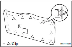
- Using a screwdriver, disengage the 14 clips and remove the trim board.
HINT: Tape the screwdriver tip before use.
12. REMOVE POWER BACK DOOR TOUCH SENSOR LH
- Remove the 4 screws.
- Using a clip remover, remove the clip and touch sensor.
13. REMOVE POWER BACK DOOR TOUCH SENSOR RH
- Remove the 4 screws.
- Using a clip remover, remove the clip and touch sensor.
14. REMOVE BACK-UP LIGHT ASSEMBLY LH (See page LI-90)
15. REMOVE BACK-UP LIGHT ASSEMBLY RH (See page LI-90)
16. REMOVE BACK DOOR GARNISH SUB-ASSEMBLY OUTSIDE
17. REMOVE BACK DOOR WITH MOTOR LOCK ASSEMBLY

- Disconnect the connector.
- Remove the 4 bolts and lock.
18. REMOVE BACK DOOR BASE STOPPER BRACKET
- Remove the 2 bolts and bracket.
19. REMOVE BACK DOOR STOPPER LOWER
- Remove the 2 bolts and stopper.
20. REMOVE REAR SPOILER COVER (See page ET-18)
21. REMOVE BACK DOOR STAY SUB-ASSEMBLY LH
22. REMOVE BACK DOOR STAY SUB-ASSEMBLY RH
 Power back door
COMPONENTS
...
 Adjustment
HINT:
On the RH side, use the same procedures as on the LH
side.
Since a centering bolt is used as door hinge mounting
bolts on the body side and the door side, the door cannot
be adjusted ...
Other materials:
Removal
1. REMOVE V-BANK COVER SUB-ASSEMBLY (See
page EM-28)
2. REMOVE NO. 1 ENGINE UNDER COVER (See page
EM-26)
3. DRAIN ENGINE COOLANT (See page CO-6)
4. REMOVE FRONT WHEEL RH
5. REMOVE FRONT FENDER APRON SEAL RH
6. REMOVE V-RIBBED BELT (See page EM-6)
7. DISCONNECT NO. 2 RADIATOR HOSE
(a) Di ...
Short to GND in Side Squib RH Circuit
DTC B0112/41 Short to GND in Side Squib RH Circuit
DESCRIPTION
The side squib RH circuit consists of the center airbag sensor assembly and
the front seat side airbag
assembly RH.
The circuit instructs the SRS to deploy when deployment conditions are met.
DTC B0112/41 is recorded when a sh ...
How to proceed with
troubleshooting
HINT:
Use this procedure to troubleshoot the engine immobiliser
system.
The intelligent tester should be used in steps 4, 5 and 7.
1 VEHICLE BROUGHT TO WORKSHOP
2 CUSTOMER PROBLEM ANALYSIS CHECK AND SYMPTOM CHECK
3 CRANK ENGINE FOR MORE THAN 10 SECONDS
4 CHECK FOR DTC
C ...
