Toyota Sienna Service Manual: Disassembly
1. REMOVE INDICATOR LIGHT WIRE SUB-ASSEMBLY

(a) Remove the indicator light wire sub assembly from the position indicator light guide.
2. REMOVE POSITION INDICATOR LIGHT BULB
(a) Remove the shift position indicator light bulb from the indicator light wire sub-assembly
3. REMOVE POSITION INDICATOR SLIDE COVER

(a) Remove the shift lever slide cover guide from the shift lever assembly.

(b) Remove the position indicator slide cover from the shift lever assembly.
4. REMOVE POSITION INDICATOR SLIDE COVER
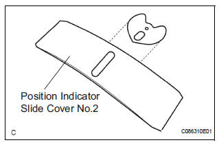
(a) Remove the position indicator slide cover No.2 from the position indicator slide cover.
 Removal
1. DISCONNECT BATTERY NEGATIVE TERMINAL
2. REMOVE FRONT DOOR SCUFF PLATE LH
HINT:
(See page IP-6)
3. REMOVE FRONT DOOR SCUFF PLATE RH
HINT:
(See page IP-6)
4. REMOVE COWL SIDE TRIM BOARD LH
HI ...
 Adjustment
1. INSPECT SHIFT LEVER POSITION
(a) When shifting from P to R position only with ignition
switch ON and brake pedal, make sure that the
shifting lever moves smoothly and can be
moderately operated ...
Other materials:
Reassembly
1. INSTALL STRAIGHT PIN
(a) Using a plastic hammer, tap in new straight pins to
the cylinder block.
Standard protrusion
2. INSTALL STUD BOLT
(a) Using E8 and E10 "TORX" sockets, install the stud
bolts.
Torque: 10 N*m (102 kgf*cm, 7 ft.*lbf) for bolt A
17 N*m (173 kgf*cm, ...
No. 2 Speaker with box
COMPONENTS
ON-VEHICLE INSPECTION
1. INSPECT NO.2 SPEAKER WITH BOX
HINT:
Remove interior parts so that the No.2 speaker with box
can be seen.
Check the speaker installation.
OK:
The speaker is securely installed.
If the result is not as specified, reinstall the No.2
s ...
Evaporative Emission Control System Incorrect
Purge Flow
DTC P0441 Evaporative Emission Control System Incorrect
Purge Flow
DTC SUMMARY
DESCRIPTION
The circuit description can be found in the EVAP (Evaporative Emission)
System.
INSPECTION PROCEDURE
Refer to the EVAP System.
MONITOR DESCRIPTION
The two monitors, Key-Off and Purge Flow, are us ...
