Toyota Sienna Service Manual: Disassembly
1. REMOVE PROPELLER SHAFT ASSEMBLY
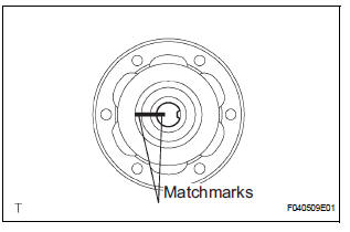
(a) Put matchmarks on both the flanges.
(b) Remove the 4 nuts, bolts and washers.

2. REMOVE INTERMEDIATE SHAFT

(a) Put matchmarks on the propeller shaft subassembly and universal joint flange.
NOTICE: Do not use a punch for the marks.
(b) Using a hexagon wrench (6 mm), remove the 6 bolts and 2 washers and separate the intermediate shaft from the propeller shaft assembly rear.
3. REMOVE CENTER SUPPORT BEARING ASSEMBLY NO.1

(a) Using a chisel and a hammer, loosen the staked part of the nut.
(b) Using SST(s) to hold the front flange, remove the nut and plate washer.
SST 09330-00021
(c) Put matchmarks on the rear flange and shaft.
(d) Hold the intermediate shaft in a vise between aluminium plates.
NOTICE: Do not overtighten the vise

(e) Using SST(s), remove the rear flange.
SST 09950-40011 (09951-04020, 09952-04010, 09953-04030, 09954-04010, 09955-04061, 09957-04010, 09958-04011)
NOTICE: Be careful not to damage the universal joint flange.
(f) Remove the center support bearing assembly No. 1 (rear) and washer.
4. REMOVE CENTER SUPPORT BEARING ASSEMBLY NO.1

(a) Using a chisel and a hammer, loosen the staked part of the nut.
(b) Using SST(s) to hold the front flange, remove the nut and plate washer.
SST 09330-00021

(c) Put matchmarks on the front flange and shaft.
(d) Hold the intermediate shaft in a vise between aluminium plates.
NOTICE: Do not overtighten the vise.

(e) Using SST(s), remove the front flange.
SST 09950-40011 (09951-04020, 09952-04010, 09953-04030, 09954-04010, 09955-04061, 09957-04010, 09958-04011)
NOTICE: Be careful not to damage the universal joint flange.
(f) Remove the center support bearing assembly No. 1 (front) and washer.
 Removal
1. REMOVE EXHAUST PIPE ASSEMBLY
(a) Remove exhaust pipe assembly (See page EX-8).
2. REMOVE PROPELLER W/CENTER BEARING SHAFT ASSEMBLY
(a) Depress the brake pedal and hold it down.
(b) Using ...
 Inspection
1. INSPECT SPIDER BEARING
(a) Check that the spider bearing moves smoothly by
turning the flange.
(b) Check for the looseness around the joint by strongly
moving the flange in the axial and ...
Other materials:
Oxygen Sensor Heater Control Circuit Low/ Oxygen Sensor Heater Control
Circuit High/ Oxygen Sensor Heater Circuit Malfunction
DTC P0037 Oxygen Sensor Heater Control Circuit Low
(Bank 1 Sensor 2)
DTC P0038 Oxygen Sensor Heater Control Circuit High
(Bank 1 Sensor 2)
DTC P0057 Oxygen Sensor Heater Control Circuit Low
(Bank 2 Sensor 2)
DTC P0058 Oxygen Sensor Heater Control Circuit High
(Bank 2 Sensor 2)
DTC P0141 Oxyg ...
Camera Picture Error
DTC 5C-40 Camera Picture Error
DESCRIPTION
DTC No.
DTC Detection Condition
Trouble Area
5C-40
Synchronous signal from the camera cannot be
transmitted.
Wire harness
Television camera assembly
Radio and navigation assembly
...
Using the mechanical key (vehicles with a smart key system)
To take out the mechanical key,
push the release button and take
the key out.
The mechanical key can only be
inserted in one direction, as the
key only has grooves on one side.
If the key cannot be inserted in a
lock cylinder, turn it over and reattempt
to insert it.
After using t ...
