Toyota Sienna Service Manual: Illumination Circuit
DESCRIPTION
Power is supplied to the radio receiver and steering pad switch illumination when the light control switch is in the TAIL or HEAD position.
WIRING DIAGRAM

INSPECTION PROCEDURE
NOTICE: The vehicle is equipped with an SRS (Supplemental Restraint System) which includes components such as airbags. Before servicing (including removal or installation of parts), be sure to read the precautionary notice for the supplemental restraint system
1 CHECK ILLUMINATION
- Check if the illumination for the radio receiver, steering pad switch, glove box or others (hazard switch, cigarette lighter, etc.) comes on when the light control switch is turned to the HEAD or TAIL position.
Result

2 CHECK HARNESS AND CONNECTOR (BATTERY - SPIRAL CABLE)

- Disconnect the spiral cable connector.
- Measure the voltage according to the value(s) in the table below.
Standard voltage

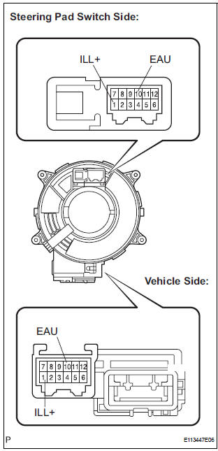
3 INSPECT STEERING PAD SWITCH ASSEMBLY
- Disconnect the steering pad switch connector.
- Connect the positive (+) lead to terminal ILL+ and the negative (-) lead to terminal EAU of the steering pad switch assembly connector.

- Check if the illumination for the steering pad switch assembly comes on.
OK: Illumination for the steering pad switch assembly comes on.
4 INSPECT SPIRAL CABLE
- Disconnect the steering pad switch and and spiral cable connectors.
- Measure the resistance according to the value(s) in the table below.
Standard resistance

NOTICE: The spiral cable is an important part of the SRS airbag system. Incorrect removal or installation of the spiral cable may prevent the airbag from deploying. Be sure to read the page shown in the brackets
5 CHECK HARNESS AND CONNECTOR (SPIRAL CABLE - RADIO RECEIVER)

- Disconnect the connectors from the radio receiver and spiral cable.
- Measure the resistance according to the value(s) in the table below.
Standard resistance

*1: 10 Speaker without Navigation System
*2: 6 Speaker with Rear Seat Entertainment System
*3: 6 Speaker without Rear Seat Entertainment System
PROCEED TO NEXT CIRCUIT INSPECTION SHOWN IN PROBLEM SYMPTOMS TABLE
6 CHECK HARNESS AND CONNECTOR (BATTERY - RADIO RECEIVER)

- Disconnect the radio receiver connector.
- Measure the voltage according to the value(s) in the table below.
Standard voltage

*1: 10 Speaker without Navigation System
*2: 6 Speaker with Rear Seat Entertainment System
*3: 6 Speaker without Rear Seat Entertainment System
7 CHECK HARNESS AND CONNECTOR (RADIO RECEIVER - COMBINATION METER)

- Disconnect the radio receiver connector and combination meter connector.
- Measure the resistance according to the value(s) in the table below.
Standard resistance

*1: 10 Speaker without Navigation System
*2: 6 Speaker with Rear Seat Entertainment System
*3: 6 Speaker without Rear Seat Entertainment System
PROCEED TO NEXT CIRCUIT INSPECTION SHOWN IN PROBLEM SYMPTOMS TABLE
 Steering Pad Switch Circuit
DESCRIPTION
This circuit sends an operation signal from the steering pad switch to the
radio receiver.
If there is an open in the circuit, the audio system cannot be operated using
the steerin ...
 Speaker Circuit
DESCRIPTION
When the vehicle has a built-in type amplifier, a sound signal is
sent from the radio receiver to the
speakers via the "6 Speaker System" circuit.
When the ...
Other materials:
Passenger Side Outer Mirror ECU
DTC B1208 Passenger Side Outer Mirror ECU
DESCRIPTION
This DTC is detected when communication between the outer mirror control ECU
RH and multiplex
network gateway ECU stops for more than 10 seconds.
DTC No.
DTC Detecting Condition
Trouble Area
B1208
Pa ...
Data list / active test
1. DATA LIST
(a) While the intelligent tester is connected to the DLC3
with the ignition switch in the ON position, the ABS
data list can be displayed. Follow the prompts on
the tester screen to access the DATA LIST.
2. ACTIVE TEST
HINT:
Performing the ACTIVE TEST using the intelligent te ...
Reassembly
1. INSTALL CENTER CLUSTER MODULE KNOB NO.6
(for Automatic Air Conditioning System)
2. INSTALL CENTER CLUSTER MODULE KNOB NO.5
(for Automatic Air Conditioning System)
3. INSTALL CLOCK ORNAMENT
4. INSTALL PRINTED WIRE INTEGRATION BOARD
SUB-ASSEMBLY (for Automatic Air Conditioning
System)
5. IN ...
