Toyota Sienna Service Manual: Installation
1. INSTALL FRONT STABILIZER BAR
2. INSTALL NO. 1 FRONT STABILIZER BAR BUSHING
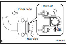
(a) Install the 2 front stabilizer bar bush No.1 to the stabilizer bar front.
NOTICE: Install the bushings with the slit facing on the rear side of the vehicle.
HINT: Install the bushing to the outer side of the bushing stopper on the stabilizer bar as shown in the illustration.
3. INSTALL EXHAUST MANIFOLD SUB-ASSEMBLY RH
HINT: (See page EM-48)
4. INSTALL MANIFOLD STAY
HINT: (See page EM-51)
5. INSTALL STEERING INTERMEDIATE SHAFT ASSEMBLY
HINT: (See page PS-21)
6. INSTALL RACK & PINION POWER STEERING GEAR ASSEMBLY
HINT: (See page PS-21)
7. CONNECT PRESSURE FEED TUBE ASSEMBLY
HINT: (See page PS-21) SST 09023-12701
8. INSTALL TIE ROD ASSEMBLY LH
HINT: (See page AH-4)
9. INSTALL TIE ROD ASSEMBLY RH
HINT: Remove the RH side by the same procedures as the LH side.
10. INSTALL NO. 1 FRONT STABILIZER BRACKET LH
(a) Install the front stabilizer bracket No.1 LH with the 2 bolts.
Torque: 17 N*m (173 kgf*cm, 12 ft.*lbf)
11. INSTALL NO. 1 FRONT STABILIZER BRACKET RH
HINT: Install the RH side by the same procedures as the LH side.
12. INSTALL CENTER EXHAUST PIPE ASSEMBLY
HINT: (See page EX-10)
13. INSTALL FRONT STABILIZER LINK ASSEMBLY LH
HINT: (See page AH-4)
14. INSTALL FRONT STABILIZER LINK ASSEMBLY RH
HINT: Install the RH side by the same procedures as the LH side.
15. INSTALL FRONT WHEELS
16. INSPECT CENTER FRONT WHEEL
17. INSPECT STEERING WHEEL CENTER POINT
18. ADD POWER STEERING FLUID
19. BLEED POWER STEERING FLUID
HINT: (See page PS-6)
20. CHECK POWER STEERING FLUID LEAKAGE
21. INSPECT AND ADJUST FRONT WHEEL ALIGNMENT
HINT: (See page SP-4)
 Inspection
1. INSPECT FRONT STABILIZER LINK ASSEMBLY LH
(a) As shown in the illustration, flip the ball joint stud
back and forth 5 times, before installing the nut.
(b) Using a torque wrench, turn the nut ...
 Rear coil spring
COMPONENTS
...
Other materials:
DTC check / clear
1. CHECK DTC (USING INTELLIGENT TESTER)
Checking DTCs.
Connect the intelligent tester to the DLC3.
Turn the ignition switch ON.
Read DTCs by following the prompts on the
tester screen.
HINT:
Refer to the intelligent tester operator's manual
for furthe ...
DVD Error/ Excess Current/ Tray Insertion / Ejection Error
DTC 44-44 DVD Error
DTC 44-48 Excess Current
DTC 44-50 Tray Insertion / Ejection Error
DESCRIPTION
DTC No.
DTC Detection Condition
Trouble Area
44-44
Operation error in the DVD mechanism
Television display assembly
44-48
Excess current is prese ...
Air outlet control servo motor
ON-VEHICLE INSPECTION
1. INSPECT AIR OUTLET CONTROL SERVO MOTOR
(a) Remove the air outlet control servo motor.
(b) Connect the positive (+) lead from the battery to
terminal 4 and negative (-) lead to terminal 5, then
check that the lever turns to "DEF" position.
(c) Connect ...
